Z-Wave Hop Count Calculator
Estimate Z-Wave route hops from distance, repeater spacing, wall attenuation, device generation, final-hop beaming support, and the classic mesh limit of four routed hops.
📌Real Z-Wave route presets
Loaded preset: Front Door Lock. The calculator checks whether the final route has enough powered hops and a beaming-capable node near the FLiRS endpoint.
⚙Route and attenuation inputs
Full route formula breakdown
📊Selected route spec snapshot
📘Z-Wave reference tables
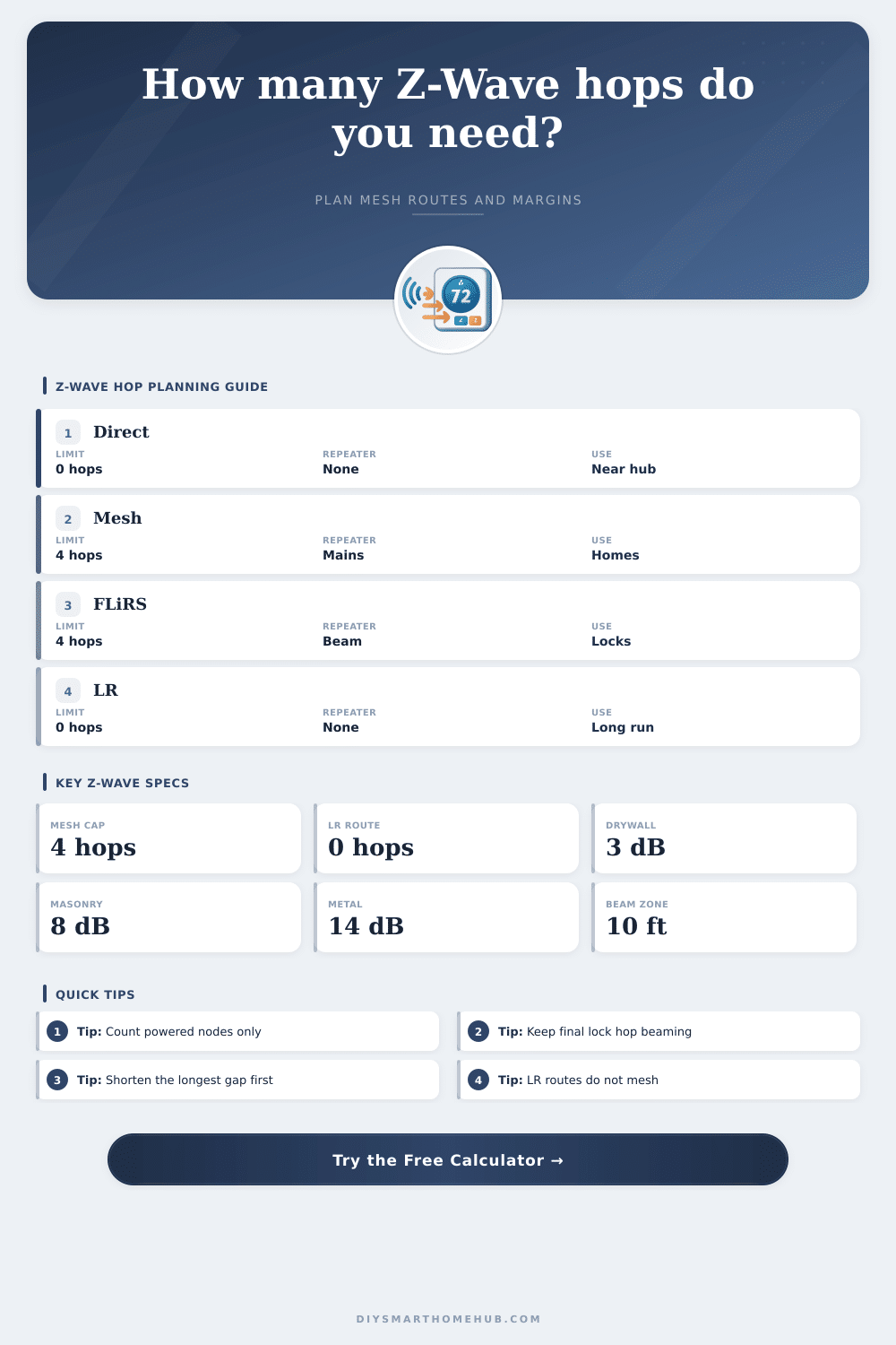
Hop limits and route behavior
| Route type | Hop count meaning | Limit used | Planning note |
|---|---|---|---|
| Direct classic mesh | 0 routed hops | No repeater | Best latency when the controller link has margin. |
| Classic routed mesh | Repeater nodes in route | Up to 4 hops | Each hop must be a listening powered node. |
| FLiRS routed endpoint | Same mesh cap | Up to 4 hops | Final routed node should support beaming. |
| Z-Wave Long Range | Direct star link | 0 mesh hops | Repeaters do not extend an LR endpoint route. |
Wall attenuation allowances
| Path profile | Modeled loss | Range tax | Typical obstacle |
|---|
Repeater placement guide
| Placement pattern | Longest gap | Hop effect | Use case |
|---|---|---|---|
| One midpoint repeater | About half route | 1 routed hop | Simple lock, garage, or basement branch. |
| Even chain | Similar gaps | 2 to 3 hops | Long hallway or multi-floor route. |
| Final beaming node | Within 10 ft / 3 m | Improves FLiRS delivery | Door locks, thermostats, and barriers. |
| Cluster near hub only | One long final gap | Poor margin | Looks dense on paper but leaves endpoint weak. |
| Classic beyond 4 hops | Too many spans | Fails route cap | Needs controller relocation or LR-capable endpoint. |
Common route presets compared
| Scenario | Distance | Needed hops | Main constraint |
|---|
🗄Z-Wave / spec comparison grid
| Z-Wave family | Routing topology | Planning span | Hop limit | Best fit |
|---|---|---|---|---|
| Classic 300/500 | Source-routed mesh | 40 ft / 12 m indoor span | Up to 4 routed hops | Dense indoor meshes with many mains devices. |
| Z-Wave Plus 500 | Source-routed mesh | 55 ft / 17 m indoor span | Up to 4 routed hops | Most mixed homes using switches, plugs, and locks. |
| Z-Wave Plus 700 | Source-routed mesh | 70 ft / 21 m indoor span | Up to 4 routed hops | Better margin in larger houses with modern nodes. |
| Z-Wave Plus 800 | Source-routed mesh | 85 ft / 26 m indoor span | Up to 4 routed hops | Longer classic routes while staying in mesh mode. |
| Z-Wave Long Range | Star, direct to hub | 400 ft / 122 m indoor plan | No mesh routing | Outdoor endpoints and long direct links to LR hub. |
💡Hop count planning tips
Z-Wave networks use a mesh system to transmit messages from one device to another device on the network. Each time the signal travel from one device to another device, that is referred to as a hop. Z-Wave uses these hops to extend the reach of the Z-Wave controller.
If the device that the user is to be control is too far from the Z-Wave controller, it will require one or more repeaters to receive the signal. A repeater is any device that is connected to a power source. Devices that use batteries cannot function as repeaters for Z-Wave signals.
How Z-Wave Signals Work and How to Use the Repeater Calculator
Distance is one of the factors to consider when establishing a Z-Wave network. However, distance is not the only factor that determine the strength of the signal that will be emitted. The signal will have to travel through physical obstructions in the path between the Z-Wave devices.
These physical obstructions will cause the signal to lose some of its strength. This loss of signal strength will make the effective distance between the devices longer then the actual distance between the devices. The calculator will ask for information about the physical obstructions between the devices.
For example, a route that includes a masonry wall will have a higher loss of signal strength than a route that includes a drywall wall. The calculator will incorporate this loss of signal strength into the calculations that the calculator performs to determine the number of repeater that will be required to establish an effective network. The calculator can use the information entered about the distance between the devices, the number of physical obstructions, and the signal loss that will result from those physical obstructions to calculate the effective distance between the devices.
Based off that calculated effective distance, the calculator can determine how many radio spans will be required for the signal to reach from one device to another. The number of radio spans will determine how many repeaters will be required to ensure that the signal does not travel further than four hops from the Z-Wave controller. The number of repeaters that you enters into the calculator will determine which devices will act as the signal repeaters.
Only mains-powered devices can act as signal repeaters. Devices that use batteries cannot act as signal repeaters. The repeaters should be placed in areas where the signal is weakest.
Placing all repeaters near the Z-Wave controller will not provide the best functioning of the network. The longest gap field in the calculator will determine the weakest part of the Z-Wave route. If the longest gap in that route is too long for the specific Z-Wave radio signal, the placement penalty will increase.
The route margin will decrease. The route margin indicates how much signal strength remains in the route after the signal has traveled the calculated distance between the devices, passed through physical obstructions, and lost signal strength due to the placement of the repeaters. If the route margin value is high, there will be extra signal strength in the route.
If the route margin value is low, there will be little extra signal strength that will remain within the route. Another factor that will affect the functioning of the established Z-Wave network is the behavior of the endpoint devices in that network. Devices that are mains powered will function with a low route margin.
Devices like Z-Wave locks, for instance, will sleep to save battery power. The lock will only wake up when it receives a beam signal. If the repeater closest to the Z-Wave lock does not support beaming, then the Z-Wave lock may not receive the commands from the network.
The beaming input in the calculator can help to account for this. Z-Wave Long Range is a different type of connection than a Z-Wave mesh network. With Z-Wave Long Range, the endpoint that is to be controlled communicates direct with the Z-Wave controller, instead of with the other devices in the Z-Wave mesh network.
Because Z-Wave Long Range does not utilize other nodes in the Z-Wave mesh network to route commands to the remote device, Z-Wave Long Range does not use hops in its connection, and does not require repeaters to extend the signal to the remote device. However, Z-Wave Long Range cannot use the classic Z-Wave mesh nodes to extend the signal to a device that is using Z-Wave Long Range. If the Long Range profile is selected in the calculator, the number of mesh hops will always be zero for this route.
To utilize the Z-Wave Long Range connection, the devices must both have a Z-Wave controller that supports Z-Wave Long Range protocols (or a bridge device that includes both technologies). The reference tables included on the page can assist in the planning of a Z-Wave network. One table includes the maximum number of hops for both classic and Long Range Z-Wave networks.
The second table includes the signal loss that can occur through different types of walls. The third table includes common placement configurations for smart home devices, as well as the constraints to those configurations. These tables can assist with the initial planning of a Z-Wave network, but are not a replacement for the signal loss measurements that a handheld signal tester can provide.
The environment in which a Z-Wave network is established may change over time. Furniture may be moved, doors may be closed, and new appliances may be placed within the rooms where the Z-Wave devices are established. Because of these changing environments, the route margin that is calculated for a route should not be treated as an exact figure that will always work for the established route.
A route that calculates to a single digit route margin may still work, but a route that calculates to a negative route margin will likely require additional repeaters to the network to work in the established environment. Classic Z-Wave networks use a four-hop limit for the signals. Each additional hop in a classic Z-Wave signal increases the latency in the communication between the Z-Wave controller and the remote device.
Latency is the time delay between communication between the two devices. Additional hops can increase the chance that the nodes in the Z-Wave network will be occupied with another node’s communication or will not be able to reach the device that is attempting to communicate with it. Thus, reducing the number of hops in the longest distance between two nodes can enhance the reliability of a Z-Wave network.
The calculator can display the number of repeaters that are required to establish a reliable network, as well as the number of repeaters that have been entered into the calculator. Many homes may employ the use of both classic Z-Wave mesh and Long Range networks. Classic Z-Wave networks can be used for devices that are close to the Z-Wave controller, while Long Range networks can be used for devices that are established away from the Z-Wave controller.
The calculator can help determine which devices should use each type of network. The goal in establishing a Z-Wave network is to create a reliable route from the controller to each endpoint device, even if the doors in the route are closed or the furnitures in the route is moved.