WiFi Fresnel Zone Calculator
Estimate the first Fresnel zone, required clearance, antenna height margin, and free-space path loss for point-to-point WiFi links.
Calculated Link Clearance
| Band | Typical use | Fresnel behavior | Planning note |
|---|---|---|---|
| 915 MHz | Long-range IoT bridge | Largest radius | Needs the most vertical clearance. |
| 2.4 GHz | Outdoor WiFi, cameras, sheds | Large radius | Good reach, but tree clearance matters. |
| 5 GHz | Point-to-point home bridge | Medium radius | Cleaner zone than 2.4 GHz at same distance. |
| 6 GHz | Short WiFi 6E links | Smaller radius | Best for clear, shorter paths. |
| 60 GHz | Very short high-throughput link | Tiny radius | Line of sight and rain fade dominate. |
| Distance | 2.4 GHz midpoint | 5 GHz midpoint | 60% clearance target |
|---|---|---|---|
| 100 ft (30 m) | 5.0 ft (1.5 m) | 3.5 ft (1.1 m) | 3.0 ft / 2.1 ft |
| 250 ft (76 m) | 7.9 ft (2.4 m) | 5.5 ft (1.7 m) | 4.7 ft / 3.3 ft |
| 500 ft (152 m) | 11.2 ft (3.4 m) | 7.7 ft (2.4 m) | 6.7 ft / 4.6 ft |
| 1000 ft (305 m) | 15.8 ft (4.8 m) | 10.9 ft (3.3 m) | 9.5 ft / 6.6 ft |
| 1 mile (1.6 km) | 36.0 ft (11.0 m) | 25.0 ft (7.6 m) | 21.6 ft / 15.0 ft |
| Obstruction | Typical height | Calculator input | Clearance interpretation |
|---|---|---|---|
| Privacy fence | 6 to 8 ft | Fence top height | Needs LOS height plus Fresnel target above fence. |
| Parked vehicle | 5 to 7 ft | Expected tallest vehicle | Use if the path crosses a driveway or parking pad. |
| Low roof edge | 8 to 14 ft | Edge height in path | Common issue on garage-to-house links. |
| Hedge or shrubs | 4 to 10 ft | Seasonal high point | Use 70% or 80% target for wet foliage. |
| Tree line | 12 ft and up | Lowest crossing branch | Raise antennas or move the path when margin is negative. |
| Project | Distance | Likely band | Design target |
|---|---|---|---|
| Room-to-room bridge | 40 ft (12 m) | 5 or 6 GHz | Full LOS usually matters more than Fresnel size. |
| Detached garage | 80 ft (24 m) | 5 GHz | Keep garage roof edges out of the zone. |
| Backyard shed | 150 ft (46 m) | 2.4 or 5 GHz | Check fences, pergolas, and hedge growth. |
| Gate camera | 300 ft (91 m) | 2.4 GHz | Use at least 60% clearance at driveway crossings. |
| Barn or workshop | 600 ft (183 m) | 5 GHz | Higher antennas are usually needed for trees. |
When attempting to transmit a WiFi signal from one building to another buildings, the radio itself is rarely the issue. The space that the signal require between the two antennas is the issue. This space is referred to as the Fresnel zone.
The Fresnel zone is an invisible area that exists around the direct line that connects the two antennas. If an object finds itself within the Fresnel zone, the signal will bend around the object or reflect off of the object, and some of the signal will weaken. This weakening of the signal may result in slow speeds, dropped connections, or connection problem for those attempting to connect to the WiFi network.
Why the Fresnel Zone Matters for WiFi Between Buildings
These connection problems may make it seem like the radios is broken, but the problems with the connections are due to the interaction between the antennas and the Fresnel zone. The first Fresnel zone is the widest portion of the Fresnel zone. The first Fresnel zone is the narrowest at the locations of the antennas.
Because the Fresnel zone is the widest at the midpoint between the two antennas, an object like a low fence that is located at the midpoint will cause more problems with the WiFi signal than a high roof that is near one of the antennas. The narrower the zone becomes between the antennas, the less of an issue an object will be for the signal. By monitoring the middle of the path between the two buildings, one can more easily understand the location of the antennas.
The frequency at which the WiFi radio’s signal transmit has a direct effect upon the size of the Fresnel zone. Lower frequencies will create wider Fresnel zones than higher frequencies. Because of this, WiFi signals that operate at 2.4 GHz will require more vertical clearance to transmit the signal than WiFi signals that operate at 5.0 GHz.
While the difference is not as apparent at shorter distances, the difference becomes more apparent at longer distances or when there are obstacles like trees along the transmission path. The higher the frequency of the WiFi signal, the smaller the Fresnel zone. However, higher frequencies will suffer more from rain, leaves, and misalignment of the antennas.
The height of the obstructions in the path only matters in relation to the line that exists between the two antennas. If the antennas are placed at the same heights, the line will remain level and easier to calculate. If, however, one antenna is higher than the other, the line between the two antennas will slope.
Furthermore, obstructions may not interfere with the line between the two antennas, but they may enter the Fresnel zone. The calculator that determines the amount of clearance required calculates the height of the line between the antennas at the position of the tallest object in the path. The outcome of this calculation provides the amount of physical gap that exists between the antennas after subtracting the size of the Fresnel zone.
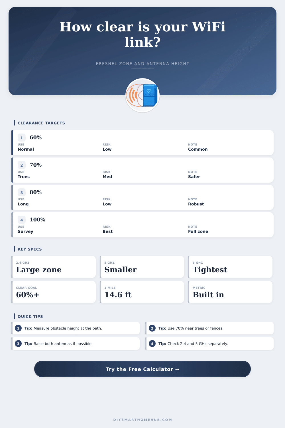
The network designer should establish the target clearance that is required for the link between the antennas. A value of 60 percent is often used as the minimum target clearance for open paths between the antennas. However, for paths that may include trees or hedgerows, a 70 percent or 80 percent target is often used so that the signal will not weaken due to leaves when the weather is wet or during the summer.
For long and permanent links between antennas, a 100 percent target is used to ensure that nothing will enter the Fresnel zone between the two antennas. The network designer chooses a percentage that the radius of the path is multiplied by as the target clearance. The resulting number is the reduced clearance that must be provided to the antennas for the link to remain stable.
Path loss is the value that the Fresnel zone calculator returns to the network designer. Path loss is a measure of how much of the signal is lost as it travels from one antenna to the other. This value is referred to as free-space path loss.
Free-space path loss is a calculation of the loss of signal at distances between the antennas, but does not include any loss due to trees, buildings, or reflections of the signal. This value helps to indicate the potential issues of signal loss between the two antennas. Path loss will be high if the path between the antennas is long.
Furthermore, if the calculated path loss value is close to the maximum range of the radio signal, there is little margin for error for other issues in the path. Real world links between antennas will rarely exist in perfect open spaces. The path may be crossed by fences, trucks, or other structures.
The obstruction table in the calculator indicates the heights of various obstructions that are common between antennas. For instance, the height of a fence top is six feet, while a tree branch may be twelve feet high. The height of the antennas must be measured from such a reference point in order to calculate the path loss and Fresnel zone.
One factor that can be altered after the installation of the antennas is the height of the antennas. Raising both antennas to the same height will keep the line between the antennas even and straight. Raising only one antenna, however, will create a slope to the line between the antennas.
The Fresnel zone calculator can provide the amount of additional height that is required for both antennas to achieve the target clearance for the link between the antennas. This value will assist the network designer in purchasing antennas that are mounted to taller masts, or in raising one antenna above the other. The band reference table is useful in selecting the proper radio frequency for the link between the antennas.
Radio signals that operate at 915 MHz have an excellent range through vegetation, but the 915 MHz signals create a larger Fresnel zone for the signal. Consequently, the antennas must often be mounted higher than the heights of the buildings in which they are to be installed. Links that use frequencies around 60 GHz have very small Fresnel zones.
Links at 60 GHz require true line-of-sight between antennas, but the links will drop if there is heavy rain between the antennas. The frequencies of 2.4 GHz and 5.0 GHz are the most common for the design of WiFi networks. Common mistakes in positioning the antennas or in measuring the obstructions between the antennas include measuring the wrong reference points.
For instance, using the height of the roof as the reference point for the antennas may result in an indicated gap that is larger than the true gap that will exist between the antennas. Furthermore, assuming that an object is at the 50 percent mark along the path between the antennas when the object is not, will result in an underestimation of the problems that the link will encounter. Lastly, failing to account for seasonal growth of vegetation along the path will result in dropped connections when the leaves begin to grow back after the winter months.
There is no way to prevent these mistakes with the calculator, but the entries for various factors will reveal any problems before installing the antennas. The output of the Fresnel zone calculator provides three types of information. First, the actual radius of the path between the two antennas at the location of the tallest obstruction.
Second, the reduced clearance that must be provided to the antennas to allow the signal to pass and remain strong. Third, the margin between the actual path between the antennas and the target clearance. If there is a large margin between the antennas, the link should remain stable between the two buildings.
If the margin is small or negative, there is a need to raise one or both antennas, or to rethink the choice of band and distance between the antennas. Thus, the calculator removes the need for arithmetic calculations to determine the variables related to the installation of the antennas.