WiFi Antenna Range Calculator
Estimate usable smart home wireless range from frequency, antenna gain, transmit power, receiver sensitivity, cable loss, and obstacles.
📍Real WiFi Link Presets
⚙Link Inputs
Estimated Link Results
📊Calculated Spec Grid
📶Band Reference Table
| Band | Typical smart home use | Strength | Range note |
|---|---|---|---|
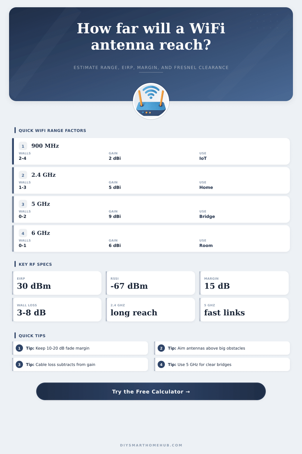
| 900 MHz | Low-rate sensors, long yard links | Best obstacle penetration | Longest reach at modest bandwidth |
| 2.4 GHz | General WiFi, cameras, IoT plugs | Balanced reach and compatibility | Good through typical interior walls |
| 5 GHz | Fast APs, bridges, streaming devices | Higher throughput and less crowding | Needs cleaner paths than 2.4 GHz |
| 6 GHz | WiFi 6E/7 rooms and close-range backhaul | Wide channels and low congestion | Best with line of sight or one wall |
📡Antenna Type Comparison
| Antenna type | Typical gain | Beam behavior | Best fit |
|---|---|---|---|
| Router dipole | 2-5 dBi | Broad omni pattern | Single room or central AP coverage |
| High-gain omni | 6-9 dBi | Flatter horizontal coverage | Longer single-floor coverage zones |
| Panel antenna | 8-14 dBi | Moderate directional beam | Garage, shed, yard, and camera links |
| Yagi antenna | 10-16 dBi | Narrow directional beam | Gate, barn, or point-to-point paths |
| Dish or grid | 18-30 dBi | Very narrow beam | Long clear outdoor bridge links |
🏠Environment Loss Factors
| Environment | Path exponent | Fade margin used | Obstacle estimate |
|---|---|---|---|
| Clear outdoor line of sight | 2.0 | 12 dB | 0-2 dB per minor obstruction |
| Light suburban yard | 2.4 | 14 dB | 2-4 dB for foliage or glass |
| Open plan indoor | 2.8 | 15 dB | 3-5 dB per drywall partition |
| Typical home interior | 3.2 | 17 dB | 4-8 dB per wall or floor |
| Dense apartment or office | 3.8 | 20 dB | 6-10 dB around concrete or elevator cores |
| Garage, masonry, or metal clutter | 4.3 | 22 dB | 8-15 dB near masonry, foil, or metal doors |
📋Common Smart Home Link Sizes
| Scenario | Typical frequency | Typical antenna gain | Planning target |
|---|---|---|---|
| Room AP to phone | 5 or 6 GHz | 2-5 dBi | -60 to -67 dBm for fast service |
| Whole-house IoT coverage | 2.4 GHz | 3-6 dBi | -67 to -75 dBm depending on device rate |
| Backyard camera | 2.4 or 5 GHz | 5-9 dBi | Keep at least 15 dB of fade margin |
| Detached garage bridge | 5 GHz | 9-14 dBi | Line of sight with clear Fresnel zone |
| Gate or barn sensor | 900 MHz or 2.4 GHz | 6-12 dBi | Prioritize link margin over peak speed |
💡Calculation Tips
The strength of the WiFi signal that reaches a house or yard depend on whether the radio signal can reach the same destination with enough strength to function. Several factors determine the signal strength. These factors include the frequency of the signal, the antenna gain, the obstacles that the signal passes through, the signal loss through the cables, and the receiver sensitivity of the devices.
These variables can all be entered into a calculator to estimate the range of the signal. The calculator can perform these calculations because each of these variables has a corresponding impact on the range of the signal. The frequency with which the signal alternates its direction affects the signal’s range.
What Affects WiFi Signal Range
Lower frequencies, such as 900 MHz, can travel farther then higher frequencies. They can also pass through the walls of a building more easily than a signal of a higher frequency. However, the data rate of a signal is slower if the frequency is low.
Furthermore, lower frequencies are often more crowded with other systems that use that frequency band. A signal of 2.4 GHz offers a balance between the range and data rate of a signal. However, the 2.4 GHz signal can be lost if it encounters several interior walls or metal appliances in the way of its path to the destination device.
A frequency of 5 GHz or 6 GHz offers a more higher data rate but has a shorter range than 2.4 GHz signals. These higher frequencies also require a clear path to the device to maintain the signal strength. The path loss exponent that the calculator use changes according to the environment in which the signal is to travel.
The antenna gain also impacts the strength of the signal. A small dipole antenna radiates its signal out in a wide pattern. This is helpful in a structure with only a few floor.
Alternatively, a panel antenna or a Yagi antenna emits its signal in a narrow beam to extend the signal to a specific location. Both of these gains are represented in the link budget that the calculator creates. The sensitivity of the signal receiver determines the strength at which the device can receive the signal.
Most mobile phones and cameras will no longer work with the signal if it reaches a level of minus sixty-seven decibels. It is always better for the signal strength to be stronger than the minimum level required. The sensitivity of the signal receiver is subtracted from the effective power of the signal.
Furthermore, the signal loss margin is also subtracted from the effective power of the signal to find the remaining budget of the signal. This remaining budget can be used to calculate the range of the signal. The number of obstacles between the router and the device can also affect the signal.
A signal can lose strength passing through drywall, but it will lose significantly more strength passing through masonry, foil-backed insulation, or a metal garage door. The number of obstacles in the path of the signal is multiplied by the loss of signal that each of these obstacles will cause to the signal. The loss factor changes according to the frequency of the signal.
The higher the frequency of the signal, the more the signal will be lost if it has to pass through obstacles. The signal can also be lost in the cables that exist between the radio signal and the antenna. Each decibel of signal loss in the cable will reduce the strength of the signal.
Furthermore, each decibel of signal loss in the cable is more important for a signal that is already weak in strength. The total loss of signal in the cables is subtracted from the transmitted signal to calculate the effective radiated power of the signal. You can increase the signal strength by using thicker cables or mounting the antennas closer to the signal transmitting radio.
The calculator will display several numbers. The range of the signal will be provided to you as one of the numbers. Another number will indicate whether the signal strength is within legal limits.
The path loss budget will show the strength of the signal after the signal passes through the obstacles. The Fresnel clearance will show the amount of space that must remain clear between the signal source and the receiving device. Branches of trees and other environmental obstacles can interfere with the signal.
Real environments are not always as calculated. The placement of furnitures, people moving throughout a structure, the changes of plants during the year, and the number of WiFi networks in the vicinity can all impact the actual signal. While the signal calculator can provide a great estimation of the signal, the only true way to determine whether the signal will reach the device is to test it with another device.
Many signal installer will first run the signal calculator. Then, after they have installed the antennas to project the signal, they will test the signal with a device to fine tune the installation. The same mathematical calculations can also be used to calculate the signal strength to a backyard camera or sensor at a gate.
However, as with extending the signal to a few floors in a residence, using a high-gain antenna to extend the signal will reduce the amount of coverage of that signal for other devices. Furthermore, the data rate of the signal can be reduced at the receiving device. This will increase the sensitivity of the receiver of that signal.
These variables can be tested in the calculator prior to purchasing the hardware or climbing the ladder to install the antenna. Overall, calculating the variables in order to ensure an even coverage of the signal will help create a stable connection. It is always best to first calculate the signal and then test it with another device.
Calculating the variables will help to ensure that you do not purchase antennas with a higher gain than are necessary to extend the signal.