WiFi Antenna Gain Calculator
Estimate antenna dBi, feed-line loss, legal-style EIRP, free-space path loss, received signal, and link margin for smart home WiFi links.
Your WiFi Antenna Gain Estimate
| Antenna Style | Typical Gain | Approx Beamwidth | Best Home Use |
|---|---|---|---|
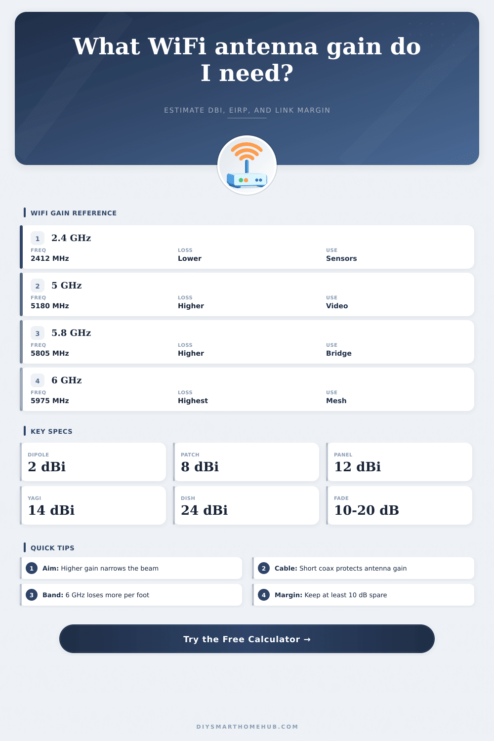
| Internal chip or trace | 1 to 2 dBi | Broad, device dependent | Small IoT boards and compact sensors |
| Router dipole | 2 to 5 dBi | Wide horizontal pattern | General indoor router coverage |
| Outdoor omni | 6 to 9 dBi | 360 degree horizontal, flatter vertical | Yard, patio, driveway, and RV coverage |
| Patch or small panel | 8 to 12 dBi | About 35 to 70 degrees | Camera, room-to-room, or short bridge links |
| Yagi or high panel | 14 to 18 dBi | About 15 to 35 degrees | Detached garage, shed, and long driveway links |
| Dish or grid | 21 to 24 dBi | About 6 to 12 degrees | Precise point-to-point links only |
| Band | Center Used | Free-Space Loss At 100 ft | Planning Note |
|---|---|---|---|
| 2.4 GHz WiFi | 2412 to 2437 MHz | About 69.8 dB | Lowest path loss and strongest wall penetration |
| 5 GHz low band | 5180 MHz | About 76.3 dB | Cleaner channels but more loss than 2.4 GHz |
| 5.8 GHz upper band | 5805 MHz | About 77.3 dB | Common for short outdoor bridge gear |
| 6 GHz WiFi 6E | 5975 MHz | About 77.6 dB | High capacity but needs closer spacing |
| Coax Type | Loss At 2.4 GHz | Loss At 5.8 GHz | When It Makes Sense |
|---|---|---|---|
| RG-174 pigtail | About 1.1 dB per ft | About 1.8 dB per ft | Very short internal pigtails only |
| RG-58 short lead | About 0.38 dB per ft | About 0.64 dB per ft | Short bench or temporary runs |
| LMR-195 / CFD200 | About 0.19 dB per ft | About 0.31 dB per ft | Common short outdoor WiFi antenna leads |
| LMR-240 / CFD240 | About 0.13 dB per ft | About 0.22 dB per ft | Moderate runs where flexibility matters |
| LMR-400 | About 0.07 dB per ft | About 0.12 dB per ft | Long outdoor antenna feeds |
| Project Type | Target RSSI | Fade Margin | Typical Antenna Choice |
|---|---|---|---|
| Battery sensor or meter reader | -72 dBm | 10 to 12 dB | Dipole or small outdoor omni |
| HD WiFi camera | -65 dBm | 12 to 15 dB | Patch, panel, or directional AP |
| Mesh backhaul node | -62 dBm | 15 to 18 dB | Panel or carefully placed omni |
| Detached garage bridge | -60 dBm | 18 to 20 dB | Matched panels or Yagi antennas |
| Long garden shed link | -70 dBm | 18 to 20 dB | High-gain panel or dish pair |
Antenna gain are a measurement of how an antenna direct the signal. Antenna gain doesnt mean that an antenna will emit more power. Instead, antenna gain mean that the antenna is focusing the antenna’s power in a specific direction.
Antennas with high gain will focus the signal into a narrow beam, permitting the signal to travel a longer distance. However, because the antenna focuses the signal into a narrow beam, the antenna will provide less coverage of an area outside of the narrow signal beam. Thus, an antenna with high gain can reach at a distant location, but the antenna may provide a weaker signal to areas outside of the narrow signal beam.
Antenna Gain and How It Affects Signal Range
Distance is one of the factors that impact the signal that reaches the destination. Distance will increase the path loss of the signal. Path loss is the reduction of the signal strength as the signal travels through space.
Path loss increase with distance and with the frequency of the signal. For instance, a 6 GHz signal will experience more path loss than a 2.4 GHz signal due to the higher frequency of the 6 GHz signal. A calculator can help convey the distance between the two antenna as a path loss figure.
Coaxial cable, or “coax,” also cause signal loss. Many individual dont account for the signal loss that coaxial cable causes. Coaxial cable loss occurs when the signal travels through the coaxial cable.
Thin coaxial cables or long coaxial cables will suffer from more signal loss than coaxial cables with a lesser gauge or length. A calculator can account for signal loss due to coaxial cables by entering the type of coaxial cable and the length of the coaxial cable. The total signal power after accounting for signal loss due to coaxial cables is referred to as the Effective Isotropic Radiated Power, or EIRP.
To increase signal strength, individuals can use shorter coaxial cables or coaxial cables with less signal loss. The type of device that will receive the signal will impact the signal strength requirements. Devices that emit small amount of data will have different signal strength requirements than devices that emit large amounts of data.
Signal fade margin can be included in the signal calculator. Fade margin accounts for environmental change to the signal path, such as trees, individuals in motion, or changes in humidity. Large fade margins will permit a signal connection to remain stable despite environmental changes.
Small fade margin may lead to signal connection failure with environmental changes. There may be physical obstacle in the signal path between the two antennas. Signal attenuation is the reduction of signal strength due to physical objects.
Antenna signal loss calculators do not account for every physical obstacle in the signal path between the antennas. Thus, an individual must account for the fade margin in the signal calculation to ensure that the signal will remain stable despite encounter physical obstacles in the signal path. A high fade margin will permit the signal to work despite encounter physical obstacles.
A low fade margin may lead to signal failures despite the signal path having minimal physical obstacles. Antenna style will depend upon the gain and coverage requirement of the link between the two antennas. Low gain omnidirectional antennas emit signals in all directions.
Such antennas are useful for covering an entire room or yard with a single antenna with low gain. High gain antennas, such as Yagi antennas or panel antennas, focus the signals into narrow beams. The gain of the antenna must match the gain requirement of the signal path between the two antennas.
Antennas has legal regulations regarding the EIRP of the antenna. The EIRP of the antenna is dependent upon the power of the radio signal, the gain of the antenna, and the signal loss due to the coaxial cable. The EIRP must be within the legal limit of the antenna.
If you increase the gain of the antenna, the power of the radio signal may have to be decrease so that the EIRP remains legal and within legal limits. The placement of the antenna will impact the strength of the signal. One way to increase signal strength is to mount the antenna at a higher location than the other antenna.
By mounting the antenna at a higher location, you can reduce the path loss of the signal. Distance between the two antennas will help to calculate the path loss of the signal. Using the distance between the two antennas will provide a more accurate calculation of signal path loss than if the location of the router is use.
Antenna gain can be used to determine how to best manage the trade-off between the distance that the signal can travel and the area that the signal cover. The antenna gain calculator can help determine the antenna gain that is required, the type of coaxial cable that should of be use, and the signal strength that the devices will need to communicate. Using an antenna gain calculator allows individuals to plan what hardware to purchase before purchasing the hardware.
Additionally, using such a calculator can help to avoid the error that can occur with the trial and error method of determining antenna placement and signal strength.