Water Underfloor Heating Calculator
Size a hydronic underfloor heating zone from heated area, design heat load, water temperatures, pipe spacing, loop limits, fluid mix, manifold layout, and heat source margin.
📌Hydronic UFH presets
🔧Room, water, and loop inputs
Hydronic UFH sizing result
Enter the room and water data, then calculate to estimate loop count, flow, pump head proxy, and heat source capacity.
📊Manifold, pipe, and spec grid
📐Water UFH room load reference
| Room or zone | Typical heat load | Common water target | Design note |
|---|---|---|---|
| Bedroom with carpet | 12-18 BTU/hr per sq ft | 95-110 F supply | Check carpet resistance and keep floor surface lower for comfort. |
| Living area with wood | 15-22 BTU/hr per sq ft | 105-120 F supply | Engineered wood usually needs moderate spacing and controlled surface temperature. |
| Kitchen or bathroom tile | 18-28 BTU/hr per sq ft | 105-125 F supply | Tile transfers heat well and can use tighter spacing for high output. |
| Insulated basement slab | 10-16 BTU/hr per sq ft | 90-105 F supply | Low temperature supply is often suitable when slab insulation is strong. |
| Perimeter glass zone | 25-35 BTU/hr per sq ft | 115-130 F supply | High-loss edges may need closer spacing or another emitter. |
📋Pipe spacing and loop planning table
| Pipe spacing | Pipe per 100 sq ft | Best use | Loop planning effect |
|---|---|---|---|
| 4 in / 100 mm | About 300 ft plus tails | Bathrooms and cold perimeter strips | Creates short dense loops with higher flow resistance. |
| 6 in / 150 mm | About 200 ft plus tails | Most living areas and kitchens | Common balance of output, loop length, and manifold count. |
| 8 in / 200 mm | About 150 ft plus tails | Bedrooms and moderate loads | Longer area per loop with lower pipe density. |
| 9-12 in / 225-300 mm | About 100-133 ft plus tails | Low-load slabs and basements | Use only when heat load and floor finish allow it. |
🌡Supply, return, and delta-T guide
| Heat source | Common delta-T | Supply range | Capacity check |
|---|---|---|---|
| Air-to-water heat pump | 8-12 F / 4-7 C | 90-110 F / 32-43 C | Lower water improves efficiency but increases flow requirement. |
| Ground-source heat pump | 8-15 F / 4-8 C | 90-115 F / 32-46 C | Works best with low floor resistance and close loop spacing. |
| Condensing boiler | 15-25 F / 8-14 C | 105-130 F / 41-54 C | Lower return temperature supports condensing operation. |
| Buffered mixed system | 10-20 F / 6-11 C | 95-125 F / 35-52 C | Use mixing controls when other emitters need hotter water. |
🔧Common hydronic UFH project sizes
| Project | Heated area | Likely loops | Typical manifold |
|---|---|---|---|
| Small bathroom | 60-90 sq ft / 6-8 m2 | 1 loop | Single port or shared nearby manifold |
| Bedroom zone | 140-220 sq ft / 13-20 m2 | 1-2 loops | 2-port manifold section for close balancing |
| Kitchen and dining | 250-450 sq ft / 23-42 m2 | 2-4 loops | 4-port manifold is a common starting point |
| Open-plan ground floor | 500-900 sq ft / 46-84 m2 | 4-7 loops | Large manifold with similar loop lengths |
| Whole-house UFH | 1200-2200 sq ft / 111-204 m2 | 8-16 loops | Multiple manifolds by floor or wing |
💡Hydronic sizing tips
Underfloor heating sounds like a magical solution for a home, but designing one are a whole different story. Either you end up with a room where it is only slightly warmer then before or you are hearing the pump whine as it tries to fight its way through a loop layout which makes no hydraulic sense at all. This is based off simple physics yet fails on complex execution.
It’s not a matter of pushing as much water through the pipes as possible. Rather, it is about spreading the heat evenly and whether your plant can do this without sounding like a noisy jet engine.
Simple Tips for Designing Underfloor Heating
This calculator handles the conversions and coefficient guesses so you can focus on the meaningful tradeoffs. Just plug in the temperature target(s), pipe spacing, and floor area, and it will do the rest.
People usually begin where most folks start: with their room size. How tightly do you intend to lay the pipes? Comfort + cost = spacing: More pipes per square foot means closer spacing. This sounds like an extra expense, but it can result in a more even floor surface at lower water temperatures. You won’t get those cold spots between tube that drive people crazy. To achieve the same heat load, wider spacing must use hotter water, not good for efficiency in air-source heat pumps. This is one little detail you’ll notice makes a difference when running up your operating costs throughout the winter.
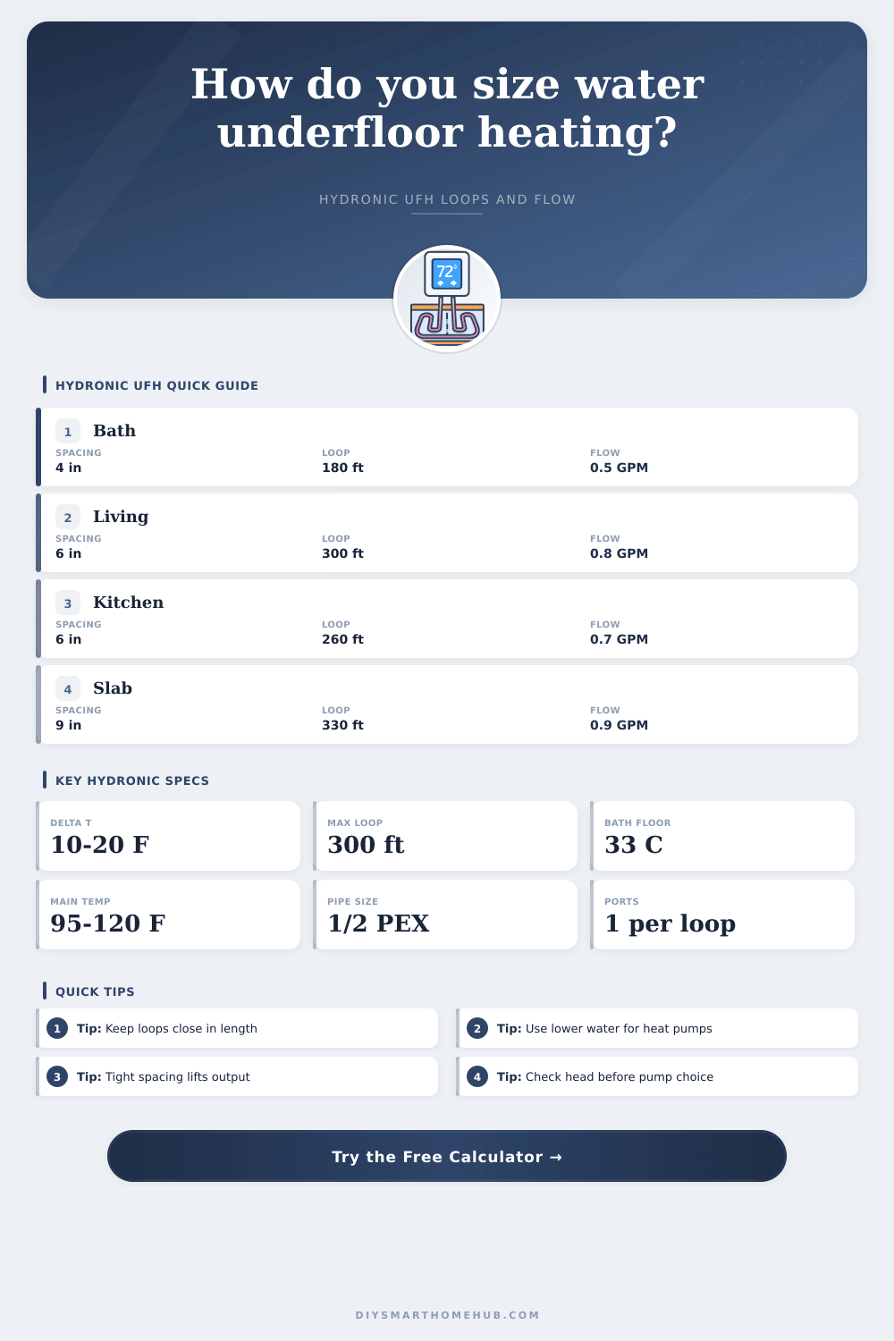
On the page, the reference table shows how pipe density change depending on the room’s function and what it’s finished with. There is also issue of the loop length. You don’t want to do one huge loop all the way around the whole house, that will be a balancing hell. As the water cools down going around the house the first couple loops is hot and the last loops cool.
Keeping the loops under three hundred feet helps make the flow equal around the manifold and evens out resistance in pipes. More similar the pressure drop. Makes it easy to balance not a maddening guessing game of trying to figure out what’s wrong with your system using balancing valves.
Respect the floor covering too. Carpet is an insulator and blocks heat from emitter. Tile conducts heat. The calculator accounts for these resistances, so do not assume that longer pipe runs require a larger heater. Placing a thick carpet over widely spaced emitters will result in never reaching design temperature regardless of how hot you run the water. Leave room for air instead. Don’t damage the finish!
The last piece of the puzzle is water temp. Lower supply temps makes your heat pump happier and create a larger delta-T (temperature spread) throughout the entire system. On the flip side, boilers handle higher returns more easily but lose their condensing advantage if the return water stay too hot. Adjusting the manifold outputs depend on what’s feeding it. If this doesn’t match up, you waste energy and/or cause short cycling.
The size of a hydronic floor depends as much on how well you distribute it as it does on brute force. Let the temperature drop where you can, respect the finishes and get loops balanced. This is the secret to an efficient quiet system that will keep your feet warm without screaming its presence at you. Usually, the comfort of what you feel underfoot hides the careful math behind it, but now you know why those numbers matter before the concrete sets.