VESA Timing Calculator
Estimate display timing totals from active pixels, porch and sync intervals, CVT reduced-blanking style estimates, refresh rate, pixel clock, scan rates, and common VESA display-interface limits.
🎯Real VESA timing presets
Presets are editable planning modes. Exact VESA/EDID timings can vary by panel, scaler, transport, and firmware, so use measured EDID values when available.
⚙Active raster and timing inputs
Full timing breakdown
📊Current timing spec summary
🖥VESA timing and display spec comparison grid
| Display spec | Usable rate | Clock signal | Typical VESA timing fit |
|---|---|---|---|
| HDMI 1.4 TMDS | 8.16 Gbps payload | 340 MHz TMDS class | 1080p120 or 4K30 with reduced chroma |
| HDMI 2.0 TMDS | 14.4 Gbps payload | 600 MHz TMDS class | 4K60 8-bit 4:4:4 or 1440p144 near limit |
| DisplayPort 1.2 HBR2 | 17.28 Gbps payload | 4 lanes, 8b/10b | 4K60 8-bit, 1440p144 8-bit with tight timing |
| DisplayPort 1.4 HBR3 | 25.92 Gbps payload | 4 lanes, 8b/10b | 4K120 with DSC or 4K98 8-bit uncompressed class |
| HDMI 2.1 FRL 40 | 35.56 Gbps payload | 16b/18b link coding | 4K120 10-bit 4:4:4 near the edge |
| HDMI 2.1 FRL 48 | 42.67 Gbps payload | 16b/18b link coding | 4K144 class or 8K60 with DSC |
| eDP 1.4 HBR3 x4 | 25.92 Gbps payload | Embedded panel link | High-res laptop panels, often with PSR or DSC |
📚Reference tables
Reduced blanking planning values
| Profile | H blank | V blank | Best use |
|---|---|---|---|
| CVT-RB v1 style | 160 pixels | 20 to 35 lines | Older PC LCD monitor modes |
| CVT-RB v2 style | 80 pixels | 32 to 63 lines | Modern high-refresh LCD timing estimates |
| CTA / CEA style | 5% to 12% | 20 to 45 lines | TV-focused video modes and HDMI sinks |
| Manual EDID | Exact values | Exact values | Panel datasheet, EDID, or measured modeline |
Porch and sync formulas
| Timing item | Formula | Unit | Meaning |
|---|---|---|---|
| Horizontal blanking | HFP + HS + HBP | pixels | Non-active pixels per line |
| Vertical blanking | VFP + VS + VBP | lines | Non-active lines per frame |
| Pixel clock | HTotal x VTotal x Hz | MHz | Total sampled pixels per second |
| Horizontal scan | VTotal x Hz | kHz | Lines scanned per second |
| Frame period | 1000 / Hz | ms | Time for one complete frame |
Common timing examples
| Mode | Total estimate | Clock class | Notes |
|---|---|---|---|
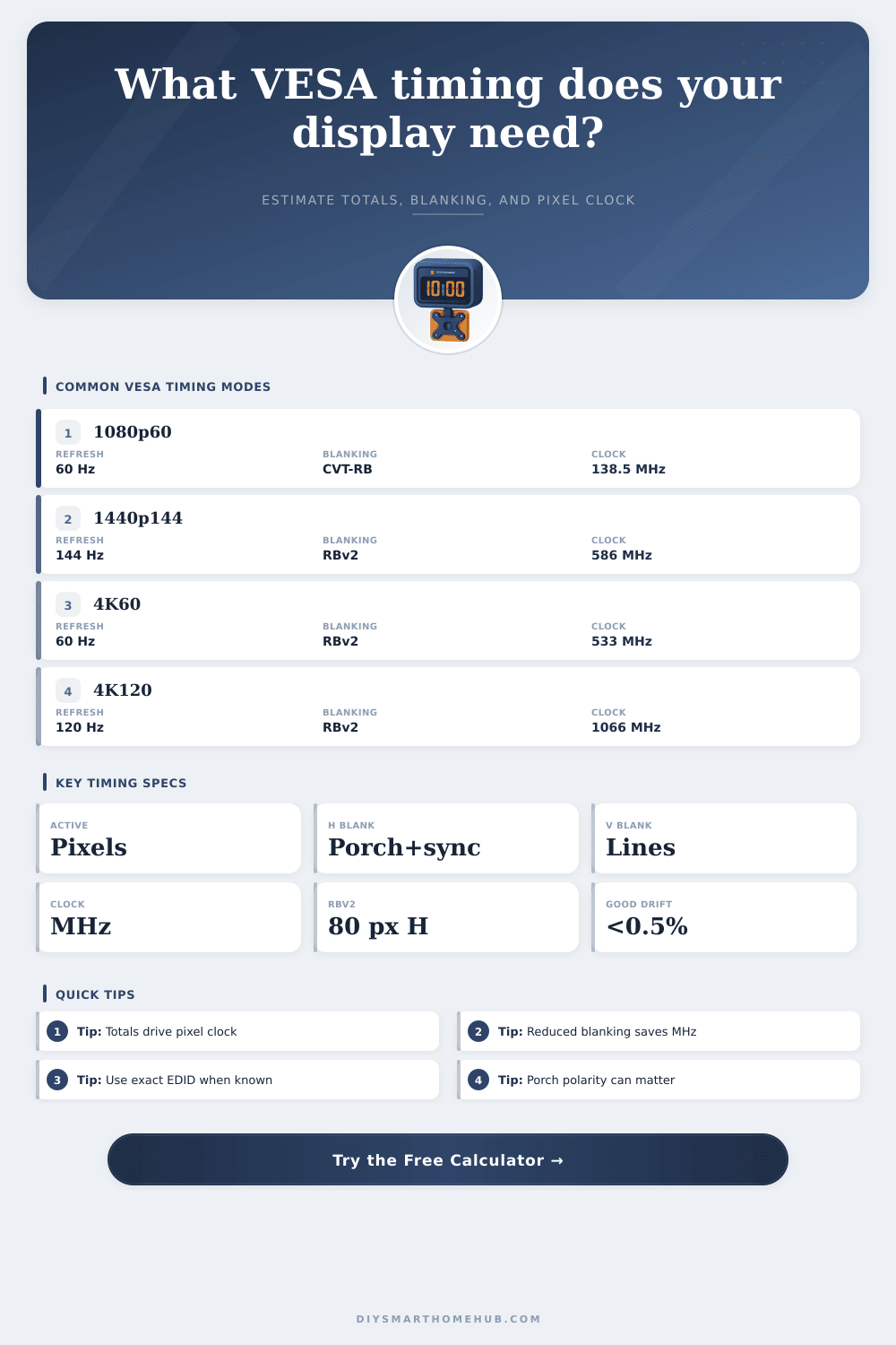
| 1920x1080 60 RB | 2080 x 1111 | 138.6 MHz | Common PC monitor reduced blanking class |
| 2560x1440 144 RBv2 | 2640 x 1481 | 563 MHz | Often close to HDMI 2.0 limits at 8-bit |
| 3440x1440 144 RBv2 | 3520 x 1481 | 751 MHz | Usually needs DP, FRL, or compression |
| 3840x2160 60 RBv2 | 3920 x 2223 | 523 MHz | 4K60 fits modern links with reduced timing |
| 3840x2160 120 RBv2 | 3920 x 2223 | 1046 MHz | High-bandwidth source and sink required |
Color payload factors
| Format | Bits/pixel | Use | Effect |
|---|---|---|---|
| RGB 8-bit | 24 bpp | PC SDR | Baseline full chroma |
| RGB 10-bit | 30 bpp | HDR desktop | 25% more than 8-bit RGB |
| RGB 12-bit | 36 bpp | Deep color | 50% more than 8-bit RGB |
| YCbCr 4:2:2 10-bit | 20 bpp | Video links | Saves one-third vs RGB 10-bit |
| YCbCr 4:2:0 10-bit | 15 bpp | TV fallback | Half of RGB 10-bit payload |
💡Timing tips
A timing calculator is use to determine the values of timing that are required for a display to work correctly. If your monitor or embedded panel displays does not lock to the display, then it is likely that the timing for that display is incorrect. Every display require the pixels to be active at the proper time, with the proper porch and sync interval.
If the timing for a display is incorrect, then the image will display in a scramble fashion; if it is correct, the image will be displayed in a clean fashion. A timing calculator can help to convert the specifications of a display into the timing values that are required to configure that display properly. The first of the values that you can enter into a timing calculator is the active raster of the display.
How to Use a Display Timing Calculator
The active raster includes the width and the height of the visible portion of the display. The active raster is the portion of the display that is visible to the user of the display; it does not include any blanking area for sync signals. If the dimensions of the active raster are altered, then each of the values for timing that the display calculates will change, as well.
For instance, active rasters of 1920 by 1080 will be different than active rasters of 2560 by 1440 due to the fact that the 2560 by 1440 display includes more pixel. The timing profile that is used with the active raster will help to calculate the horizontal and vertical total for the display. The pixel clock for the display will be calculated from these horizontal and vertical totals, rather than from the active raster value.
Porch intervals and sync intervals will be required for the display. The horizontal front porch will allow for the beam to stabilize before the sync signal to arrive at the display, and the horizontal back porch will allow for the display receiver to prepare for the next line of the display. Even moddern flat panel displays require each of these intervals; devices like scalers, transmitters, and receivers require these sync signal to function properly.
These settings can be switched between CVT reduced blanking profiles and traditional video profile. Reduced blanking profiles reduce the size of the porch and sync intervals; this can save bandwidth for the display link. However, using such a profile can create issues for the displays with a sink that requires sync signals of a specific width or polarity.
For these displays, if any image rolling or sparkles are seen after switching to the reduced blanking profile, it may be necessary to check whether the sink has accepted the updated horizontal and vertical totals. The timing calculator will display the pixel clock as one of the main output from the timing calculator. The pixel clock is measured in megahertz, and will indicate whether a specific link to the display, such as HDMI 2.0 or DisplayPort 1.4, can support the selected display mode.
For instance, HDMI 2.0 may have a limit of 600 megahertz for its TMDS clock; if the calculated pixel clock exceeds this value, it may be necessary to reduce the color depth of the image. In addition to the pixel clock, the timing calculator may also provide an estimate of the raw payload of the display link in gigabits per second. For example, using a ten-bit RGB color format will result in a display link that has 25% more data to transmit than one that is using an eight-bit RGB color format; thus, a ten-bit color format will require more bandwidth to transmit the image properly.
The refresh rate is one of the main component of timing calculations. For example, a refresh rate that works for a display mode at 60 hertz may not allow for the same display at 144 hertz; the refresh rate for the display will multiply the horizontal and vertical totals. Thus, refresh rates in the form of 59.94 or 119.88 can be entered.
Additionally, the horizontal scan rate can be calculated in kilohertz; this value is useful for displays with a line rate limit for the panel; if the calculated value is too high, the panel may refuse the mode. In most instance, the specifications that the timing calculator calculates will not match the actual displays from the hardware device that is connected. As the signal travels from the source to the sink, any cables will introduce jitter into the signal, the transmitter will output the signal with a degree of tolerance, and the receiver will require additional line for blanking.
Additionally, older embedded panels may not include these specifications in their description of the panels. Thus, fields for entering a custom pixel clock limit for the hardware device can be provided; the pixel clock for any scaler or bridge chip can be entered into this field. This field is also helpful for older embedded panels, as it is one of the only specification that may be listed for the panel.
Color formats may change the payload of the data that is sent along the display link. For example, if a four-two-two sampling format is used, the horizontal chroma resolution will be halved, and the data rate will be halved, as well. By displaying these value for the payload in various color formats, the user can decide whether the bandwidth savings for a four-two-two format are worth any potential loss of color quality from the display.
Additionally, the timing calculator will not display the way the image will appear on the display, but it will indicate whether the link has the capability to carry the chosen color format. Comparison table can be provided to the user, listing the amount of usable payload that the link can transmit in various example of display interfaces. These table will also include information regarding the clock class of the link.
Both of these value will help the user to compare the calculated values to the display link that is being used. For both categories of values, the tables will note that the throughput of the link may be less under real world application than what is published for that link; audio data, metadata, and guard bands for the display links may reduce the available throughput of the link to the display device. An error that is common among those that use these timing calculators is assuming that the active resolution of the display is the only important factor.
For example, an individual may enter an active resolution of 3840 x 2160 into the calculator, but not consider whether the other factor will allow for the link to support such a display. Another of the common errors is copying the porch intervals and sync intervals from one profile to another without ensuring that they are the same for both profile. These value will be displayed on the calculator, allowing for any difference between the profiles to be noted before the timing is entered into the display device’s firmware.
Timing is a negotiation between the source device, the link between the devices, and the sink device; a timing calculator provide the numbers to that negotiation. Beyond entering the horizontal and vertical totals, the other values can be entered into the firmware of the display device; however, it is also recommended to enter the horizontal and vertical totals into the display device’s EDID. Measured value for the sink will be more accurate than the estimates provided by the timing calculator, but these estimate will help an individual to determine which display mode they should test on the display device.