3 Phase Voltage Drop Calculator
Estimate line-to-line voltage drop for a three-phase feeder or branch circuit using load current, power factor, conductor resistance, reactance, temperature, and parallel run data.
📌Real 3-phase scenarios
📏Circuit and conductor inputs
🔍Live electrical notes
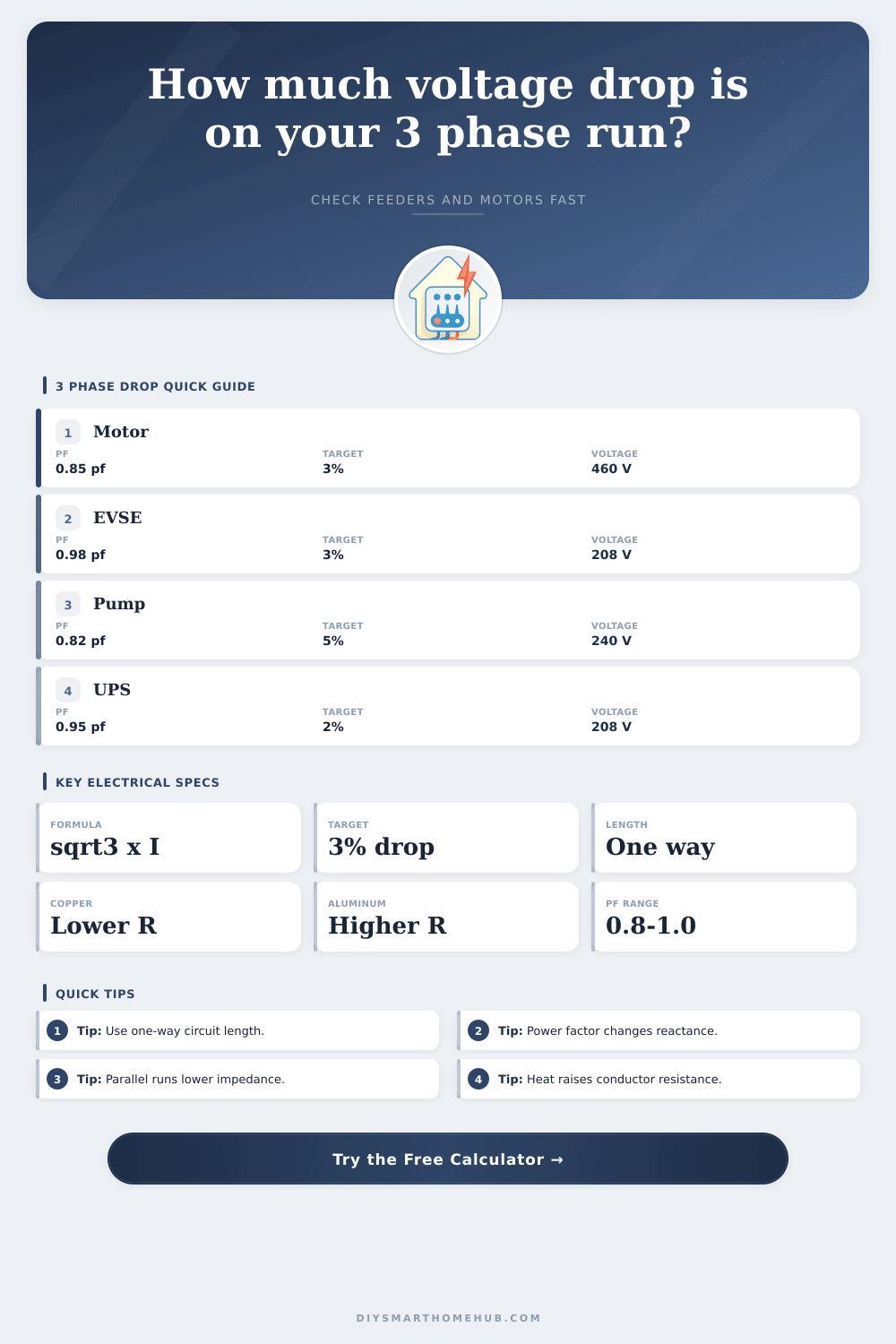
📊Device and spec comparison grid
📘Conductor resistance reference
| Size | Copper ohm/kft | Aluminum ohm/kft | Copper amps | Aluminum amps | Typical use |
|---|
🔧Raceway reactance reference
| Profile | X ohm/kft | Best for | Model note |
|---|
🔌Load profile reference
| Load type | Typical PF | Drop target | Why it matters |
|---|
📋Preset comparison table
| Scenario | Voltage | Load | Run | Conductor | Est. drop |
|---|
Resistance and reactance values are planning references for estimating voltage drop. Final conductor sizing should be checked against the applicable electrical code, terminals, ambient conditions, and equipment nameplates.
Voltage drop occur in electrical circuits when the electrical power is sent across a distance. In doing so, some of the power is “lost” before it reaches the electrical load. Voltage drop is the loss of the voltage of an electrical circuit.
Voltage drop becomes a critical factor if you are feeding motor, chargers, or other electrical equipment. Due to the way that three-phase power is distributed, the math behind calculating voltage drop for a three-phase circuit is performed differently than the math for calculating voltage drop for a single-phase circuit. The calculator help to perform that math for you; it saves you the effort of having to calculate the problem yourself, and it allows you to better understand the results of that calculation.
Three Phase Voltage Drop and How to Use the Calculator
Three-phase power distribute the electrical load across three conductors, with each conductor offset in time from the other two. Because of this offset in time, three-phase circuits provide more electrical power with the same amount of copper than single-phase circuits provide. The formula for voltage drop for three-phase circuits include the factor of the square root of three; this factor is inherent to the three-phase system’s geometry.
The square root of three is included in the equation because the voltage that is measured between lines in the three-phase system is not the same as the voltage of the individual conductors. Additionally, the load on three-phase circuits can be expressed in terms of amperage, kilowatts, or horsepower; these two units is related to each other, so when the load is entered in terms of one unit, the calculator will also change that value to the other unit. Power factor is a variable that many people disregard when calculating voltage drop.
Yet, power factor is a variable that should be considered because it affect how much electrical energy is performing useful work. Three-phase motor and pumps do not tend to operate at a power factor of one; they do not have a unity power factor. As a result of the power factor not being one, the current within the conductors can either lead or lag the voltage in those circuits.
Additionally, as the power factor decreases, the impedance of the circuit increase; it becomes harder for the system to deliver power to the motors and pumps at the same rate. It is for these reasons that a power factor must be entered into the calculator; the angle of the power factor weights the resistance of the system, and the complement of that angle weights the reactance of the system. The length of the conductor will be one of the inputs into the calculator.
However, the length that should be entered is the one-way distance. This one-way distance is used in the calculation because the three-phase equation account for the round-trip journey of the electricity in the conductor. Should the round-trip distance be entered into the calculator instead, the voltage drop will be overrepresented.
Additionally, another of the variables that should be represented is the operating temperature of the conductor. The resistance of the conductor will change based on its temperature; the longer the conductor heats up, the more the resistance increase. Thus, the calculator adjusts the reference of the resistance of the conductor to reflect the operating temperature of the conductor.
Yet another factor to consider is the number of sets of conductors running in parallel with each other. The more sets of conductors that is running in parallel with each other, the less the resistance and reactance of the system will increase. Thus, this variable is another that should be entered into the calculator.
There are four specific outputs to the calculator. Each output present the user with specific information about the electrical circuit that was entered into the calculator. For instance, the line voltage drop will present the user with the number of volts that is lost between the power source and the electrical load.
The percent drop will provide the user with information about the voltage drop in relation to the system voltage and the target voltage drop. The receiving voltage will display the actual voltage that will be delivered to the electrical equipment. Finally, the heat loss will calculate the amount of watts that are lost as heat in the circuit; this value is useful if the electrical installation is concerned about heat build-up within conduits, for instance.
These outputs will not replace the need for an ampacity calculation, but they will help to determine if the electrical conductor that was selected will behave in the way that the electrical designer for the installation expects it to. When making electrical installation decisions, tradeoffs must be made. The tables that is provided here illustrate some of the tradeoffs that may need to be made.
For instance, copper conductors are more expensive than aluminum conductors, yet copper have a lower resistance than aluminum of the same size. Aluminum is lighter in weight than copper, yet it cost less than copper; however, due to the higher resistance of aluminum, a larger cross-section is required to move the same amount of power (or reduce the voltage drop) as copper. Additionally, the type of raceway (conduit) that is used in the electrical installation will impact the reactance of the circuit.
Finally, the type of load that is to be distributed along the circuit will impact the electrical installation requirements; different types of electrical equipment require different level of voltage regulation. The conditions of an electrical installation may not always match the ideal conditions that were made for the calculations that the calculator performs. For instance, ambient temperature may change the temperature of the conductors.
Additionally, a loose electrical termination may change the resistance of the conductor. Furthermore, motors may draw high amounts of starting current that is much higher than the current that is drawn when the motor is in running mode. For these reasons, it may be necessary to size the conductor according to the starting current of the motors.
One habit that may be utilized for electrical installations that contain motors is to run the voltage drop calculation twice. Once when the electrical load is set to the running load of the motors and equipment, and again when that electrical load is set to the starting current of those motors. Another factor to consider is that the receiving voltage may change.
Yet another factor to consider is that the goal of the voltage drop calculation is not to achieve a voltage drop of zero; rather, the goal is to ensure that the voltage that is delivered to the electrical load stay within the range that the electrical equipment’s manufacturer rates for that equipment.