Smart Motion Sensor Detection Distance Calculator
Estimate practical detection distance, coverage width, floor coverage, blind zone, and confidence for PIR, mmWave, and ultrasonic smart home motion sensors.
📌Real motion sensor presets
⚙Sensor geometry and target inputs
PIR wall lens
PIR range depends heavily on warm target size and crossing motion through lens zones.
Confidence score updates after calculation.
Detection distance results
Full calculation breakdown
📡Motion sensor and spec comparison grid
📊Reference tables
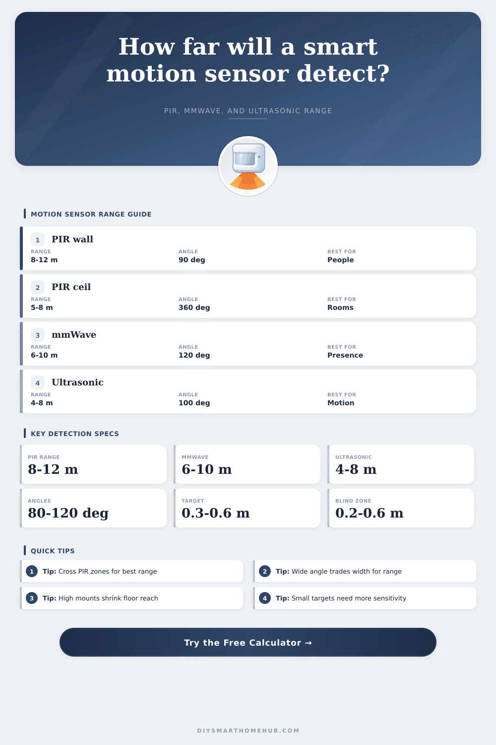
Technology range and behavior table
Typical smart-home values for comparing PIR, mmWave, and ultrasonic sensors before applying the calculator corrections.
| Sensor type | Typical rated range | Best movement | Field behavior | Main correction in calculator |
|---|---|---|---|---|
| PIR wall lens | 8 to 12 m, 26 to 39 ft | Crossing warm bodies | Lens zones spread horizontally | Target size x motion path x height |
| PIR ceiling 360 | 5 to 8 m diameter reach | Crossing below lens zones | Wide field, shorter far reach | Height penalty and wide-angle penalty |
| mmWave wall | 6 to 10 m, 20 to 33 ft | Approach, presence, micro motion | Beam can see through light obstacles | Radar target factor and angle factor |
| mmWave ceiling | 4 to 8 m room reach | Presence in occupied zones | Broad room occupancy pattern | Mount height and micro-motion factor |
| Ultrasonic wall | 4 to 8 m, 13 to 26 ft | Small movement in enclosed rooms | Reflections fill room volume | Reflective target and height factor |
| Ultrasonic ceiling | 3 to 7 m practical radius | Desk, office, restroom motion | Soft surfaces reduce practical reach | Acoustic target and geometry factor |
Field angle geometry table
Far-end width is calculated as 2 x range x tan(field angle / 2). Very wide fields give more width but lower far-distance density.
| Horizontal angle | Width at 5 m | Width at 10 m | Coverage style | Range effect used |
|---|---|---|---|---|
| 45 degrees | 4.1 m, 13.6 ft | 8.3 m, 27.2 ft | Narrow corridor beam | Small range boost |
| 90 degrees | 10.0 m, 32.8 ft | 20.0 m, 65.6 ft | Common wall corner | Reference wall field |
| 120 degrees | 17.3 m, 56.8 ft | 34.6 m, 113.6 ft | Open room wall field | Moderate range trim |
| 180 degrees | Very wide edge field | Very wide edge field | Fan or half-room lens | Stronger range trim |
| 360 degrees | Circular room coverage | Circular room coverage | Ceiling occupancy field | Diameter-style coverage |
Preset comparison table
These values are generated from the same formulas as the calculator presets, so they show realistic differences between sensor choices.
| Preset | Sensor inputs | Effective range | Coverage | Confidence |
|---|
Formula reference table
The model keeps the sensor type separate from geometry so PIR, mmWave, and ultrasonic results do not collapse into one generic range multiplier.
| Formula step | Expression used | Why it matters | Sensor-specific behavior |
|---|---|---|---|
| Target factor | (target / reference) exponent | Small targets present less thermal, radar, or acoustic signal | PIR uses 0.50 exponent, mmWave 0.25, ultrasonic 0.40 |
| Height factor | 1 - height error / tolerance | Mounting too high or low shifts zones away from the target | Ceiling models have different ideal heights than wall models |
| Angle factor | (reference angle / field angle) exponent | Wider fields dilute far-edge detection density | Ceiling 360 models are capped separately from wall beams |
| Coverage width | 2 x range x tan(angle / 2) | Converts distance into far-end monitored width | 360 degree sensors use circular diameter instead of infinite tangent |
| Coverage area | 0.5 x radians x radius squared | Estimates the floor wedge between blind zone and far range | 360 degree sensors use a circular floor area model |
✅Detection calculation tips
Smart motion sensor can detect movement within the sensor’s field of view and trigger some action, like turning on lights. However, many people often find themselfs frustrated when the motion sensor fail to turn on the lights when they move through the space. These sensors must be matched to the area that is to be monitored as well as to the way in which people moves within the area.
For instance, the way that individuals move through a hallway is likely to be different than the way that they are sitting in a bedroom. The detection distance of the motion sensor can be a difficult parameter for the person to understand, as the detection distance that is printed on the sensor box is based upon ideal conditions within the sensor box. However, the real world is often different than the ideal world described in the sensor box.
How Motion Sensors Work and Where to Put Them
For instance, if the sensor is to detect a person walking direct towards the sensor, the detection distance will be less than if the individual was walking across the detection zones of the sensor. The same is true of if the height of the sensor is higher than that which is printed on the sensor box. There are a variety of sensor technology that can be used in a motion sensor, each reacting differently to movement.
For instance, PIR sensors will detect the presence of movement by monitoring the changes in heat within each of the segmented lens of the sensor. However, a person sitting in one place will not create enough changes in heat for the sensor to activate. Radio wave sensors, known as mmWave radar sensors, will emit radio waves into the area and analyze for any shifts in the waves (known as Doppler shifts) to indicate movement within the area.
These sensors can detect very small movements, such as breathing. Lastly, ultrasonic sensors reflect sound waves off of the objects in the area. These sensors are often strong in enclosed spaces, but can be affected by soft materials that absorb the reflected sound waves, such as curtains or carpets.
The mounting height at which the sensor is mounted into the area to be monitored can create several compromise in the sensor. For instance, mounting a PIR sensor too high on a wall will cause a blind zone to be created. A blind zone is an area within which a person can stand in which the sensor will not detect the person.
Additionally, mounting the sensor too low on the wall will cause problems in areas of the room to be missed by the sensor. Ceiling sensors can often eliminate these mounting height problems but may have less distance in its detection. The tilt angle of the sensor also impacts the way that the sensor will monitor the area.
If the sensor is mounted on a wall, the sensor will “see” further into the area with a downward tilt angle than with a tilt angle that leans into the wall. Therefore, the tilt angle should also be factored into the sensor calculation. The size of the target that the sensor detects will change how the sensor react.
For instance, an adult walking through an area will leave a larger signal on the sensor than a child, a pet or a person with their hand extending out into the area. The sensitivity of the sensor can be adjusted to detect these small targets, but doing so will likely cause false alarm. The direction of movement of the target can also impact the movement that the sensor detects.
For instance, PIR sensors work best for detecting movement that crosses the detection zones of the sensor. If a person walks directly toward the sensor, the number of detection zone that is crossed is reduced, which reduces the detection range for that sensor. Additionally, movement that is lateral or diagonal to the detection zones creates the strongest signal by the sensor.
In contrast, sensors that use radio waves or sound waves to detect movement will not be impacted by the movement of the target directly towards the sensor; they will detect the same type of micro-motions that occur in small areas. Therefore, the movement path of the target can be entered into the calculation to determine its impact on the sensor. Another factor to consider is the blind zone of the sensor.
These are areas near the sensor that the sensor will not monitor for movement. The size of these blind zones will increase if the mounting height of the sensor is increased, or if the tilt angle of the sensor is increased towards the ceiling. These blind zones may be problematic in areas like stairwells, where it is important to monitor the first few step.
Additionally, the horizontal field angle of the sensor creates the width of the coverage of the sensor at the far end of its range. The tables provided on the sensor box provide typical values for the detection distance, range and other features for each type of sensor. These tables are not meant to replace the measurements that can be made of the space that is to be monitored by the sensor, but they can help the person to understand if a PIR sensor that detects 10 meters of movement is the same as a mmWave sensor that detect 6 meters of movement.
The preset buttons for the sensor calculation allow a person to set the parameters to calculate detection distance for various scenarios. For example, a hallway and a living room can be calculated with the push of a button. The effective range, the width of the detection area and the blind zone can all be calculated.
These values can then be compared to the use of the space to determine if the sensor will fulfill its purpose within that room. Additionally, each sensor will have a confidence score associate with its calculation. This score is a representation of how well the settings for the sensor match the sensor, but it isnt a guarantee that the sensor will perform in the way that is expected.
Being able to calculate these variable allows the user to avoid guesswork in determining how the motion sensor will interact with the area. The parameters of the installation of the sensor can be varied and their impacts on the sensor can be seen. By understanding each of these variables prior to installing the sensor into the area that is to be monitored, the lights will not behave in a way that was not expected by the individual installing the sensor.
Therefore, the motion sensor will work effective when it can detect the movement of the person entering the room.