Short Circuit Rating Calculator
Estimate available fault current at an equipment bus, then compare it against assembly SCCR, protective-device interrupting rating, and a listed series rating using transformer impedance, utility source strength, conductor impedance, and feeder distance.
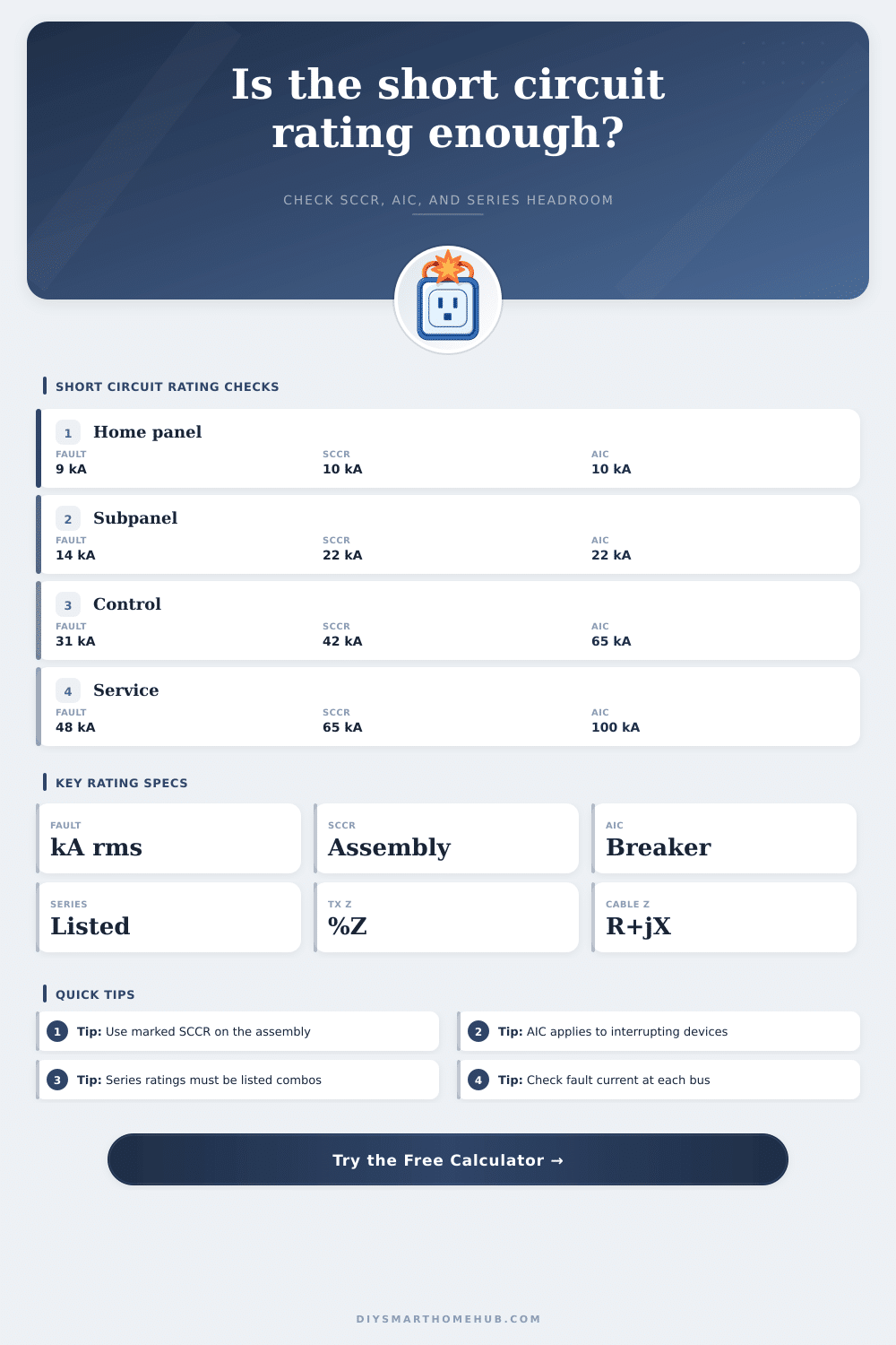
📌Short circuit rating presets
⚙Rating inputs
🔎Live rating cues
📊Electrical/spec comparison grid
📘Conductor impedance table
| Conductor set | R ohm/1000 ft | X ohm/1000 ft | Parallel sets | Best use in this calculator |
|---|---|---|---|---|
| #2 copper | 0.194 | 0.048 | 1 | Residential feeders and small smart subpanels. |
| 1/0 copper | 0.122 | 0.046 | 1 | Long subfeeds where impedance visibly reduces kA. |
| 500 kcmil copper | 0.0258 | 0.040 | 2 or 3 | Service switchboards, large panelboards, and high SCCR assemblies. |
| 4/0 aluminum | 0.101 | 0.048 | 1 | Detached building and automation feeder estimates. |
| 500 kcmil aluminum | 0.0435 | 0.041 | 2 | Large aluminum service or distribution feeder estimates. |
🧮SCCR, AIC, and series rating comparison
| Rating term | What it protects | Calculator comparison | Pass cue | Important limit |
|---|---|---|---|---|
| Available fault current | Electrical bus location | Calculated from source, transformer, and feeder Z. | Lower than each applicable rating. | Must be checked at the actual equipment location. |
| SCCR | Assembly withstand rating | Equipment SCCR minus calculated available kA. | Positive headroom, preferably with a buffer. | Not the same as a breaker interrupting rating. |
| Interrupting rating | Breaker or fuse opening fault | Standalone AIC minus available kA. | Positive headroom at the protective device. | Device must be rated for system voltage and type. |
| Series rating | Listed upstream/downstream combo | Series kA minus available kA. | Positive headroom only when the exact combo is listed. | Cannot be invented from separate device ratings. |
📐Formula reference table
| Step | Three-phase formula | Single-phase formula | Why it matters |
|---|---|---|---|
| Transformer FLA | kVA x 1000 / (1.732 x V) | kVA x 1000 / V | Base current used before applying transformer percent impedance. |
| Transformer fault | FLA / (%Z / 100) | FLA / (%Z / 100) | Maximum transformer terminal current with an infinite source. |
| Conductor impedance | (R + jX) x length / sets | 2 x (R + jX) x length / sets | Single-phase faults use an outgoing and return conductor path. |
| Available current | V / (1.732 x total Z) | V / total loop Z | Short-circuit current available at the selected equipment bus. |
| Headroom | rating kA - available kA | rating kA - available kA | Used for SCCR, interrupting rating, and series rating comparisons. |
🏠Common rating scenarios
| Scenario | Typical voltage | Common marked rating | Fault-current behavior | Rating check focus |
|---|---|---|---|---|
| Home load center | 120/240 V | 10 kA or 22 kA | Often transformer-limited, but short services can be high. | Panel SCCR and main breaker AIC. |
| Detached garage subpanel | 120/240 V | 10 kA or 22 kA | Long feeder impedance can reduce the available kA sharply. | Load-end available current at the subpanel. |
| EV or smart energy panel | 208 V or 240 V | 22 kA to 65 kA | Higher transformer kVA can outrun small-panel ratings. | Assembly SCCR and breaker AIC together. |
| Automation control cabinet | 208 V or 480 V | 5 kA to 65 kA | Control components can set the assembly SCCR below the OCP AIC. | Marked SCCR, not only upstream breaker rating. |
| Service switchboard | 480Y/277 V | 65 kA to 100 kA | Utility source contribution and low transformer Z dominate. | Interrupting rating and equipment series documentation. |
💡Rating tip boxes
Every electrical systems has an invisible ceiling for the amount of current that can travel through a short circuit. This value is one of the most important value for electrical safety. A short circuit rating calculator can help to determine the current ceiling at a specific piece of equipment.
This calculator determine the short circuit current by using several specific input. These include the strength of the utility source, the impedance of the transformer, and the resistance and reactance of the conductors. Based off these values, the calculator display the margin between the current that is available to travel through the short circuit and the values that are stamped on the equipment, the circuit breakers, and the series combination of electrical components that are listed for that equipment.
What a Short Circuit Rating Calculator Does
Each of these value has a purpose and is needed to calculate the short circuit current value for a specific installation. For example, the size and impedance of the transformer will determine the maximum amount of current that the transformer can produce. A 150 kVA transformer with 2 percent impedance will have less available fault current than a 500 kVA transformer with 6 percent impedance.
Additionally, the size of the conductors, the material of the conductors, and the length of the conductors will all reduce the maximum current that is available to travel through the circuit. The longer that the conductors travel from the power source to the electrical equipment, the more the fault current will drop at the equipment. A subpanel that is located at the end of a long feeder run will have less available fault current than the service panel that power that subpanel.
The short circuit rating calculator also separates these three different value because many people is unaware of the difference between these three ratings. The first of these ratings is the short-circuit current rating of the equipment, or SCCR. This value indicate the electrical rating of the equipment assembly as a whole.
After this, the interrupting rating, or AIC, belong to the circuit breaker. The third of these ratings is the series rating. This is a narrow rating that only apply to specific electrical devices that are listed as a series combination with one another.
The calculator display the headroom that exists against each of these values to indicate the electrical safety of the installation. Although short circuit rating calculators consider the variable of the installation, there are many other variables that may impact the short circuit rating of the electrical installation. For example, if the utility company that is supplying the power to the installation increases the size of the transformers, the short circuit rating calculator will not be able to account for this.
Additionally, if the conductors experience a change in temperature, the resistance in the conductor will change. Other variables that may impact the short circuit current and that the calculator will not account for include the number of sets of conductor that are running in parallel, if there are any, control cabinet, and the individual component of those control cabinets. Each of these variables will change the outcome of the calculation that the calculator can provide for the electrical installation.
Therefore, the results of the calculator are only an estimate of the short circuit current for the electrical installation. To determine if the electrical installation is safe, the calculated short circuit current must sit below the listed ratings for the equipment at that specific location. Additionally, you must make the determination as to whether the installation is relying on a narrow margin for fault current or whether the installation is relying on the rating of a series combination of electrical component.
If the calculated fault current is close to the rating of the electrical equipment, then even small changes in the length of the feeder run or the size of the conductors can alter the outcome of the calculation. It is recommended that you perform the calculation prior to ordering the electrical equipment. By calculating the short circuit current prior to ordering the electrical equipment, it will be possible to determine whether adjustment to the order are necessary to ensure the safety of the installation.
The same logic can be used to calculate the fault current for a residential load center, EV charger panel, or a motor control cabinet. The variables will remain the same. Even if the voltage class and the amount of available space for the electrical equipment changes, the calculation of the short circuit current is still performed at the actual location of the electrical equipment.
It isnt necessary to calculate the short circuit current of a panel at the terminals of the transformer supplying power to that panel. The assumption that the current and voltage ratings of the service panel are applied to the electrical equipment that is located at the end of the feeder run is a common mistake that can occur in the installation of electrical equipment. The margin for error for fault current will dissapears after the current traverse through a few hundred feet of electrical conductor.
By performing this single calculation of the short circuit current, the installation can be built with confidence that the calculations will remain accurate when the utility company delivers the final letter indicating the fault current of the installation.