Service Entrance Wire Size Calculator
Estimate service entrance conductor size from service rating, calculated load, copper or aluminum ampacity, terminal temperature, ambient correction, parallel sets, run length, and voltage drop.
📌Service conductor presets
🔧Wire sizing inputs
Service entrance wire sizing result
Enter service details, then calculate to see the recommended conductor and voltage-drop check.
⚙Conductor sizing spec grid
📊Common service entrance conductor sizes
| Service scenario | Ampacity target | Copper 75 C starting point | Aluminum 75 C starting point |
|---|---|---|---|
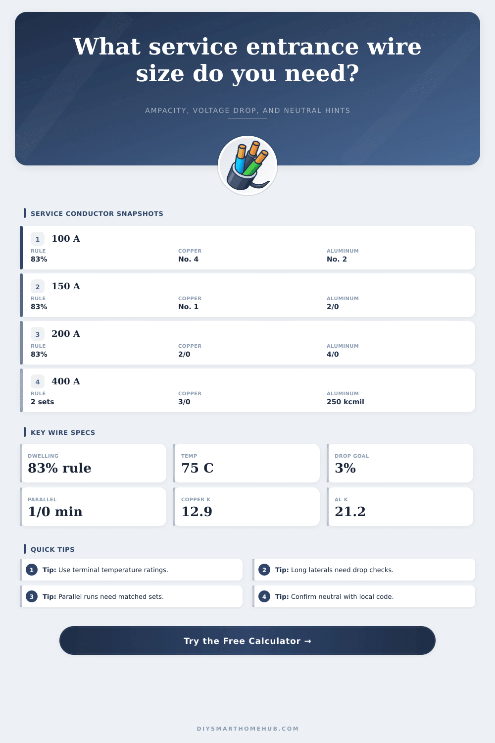
| 100 A one-family dwelling | 83 A minimum before load check | No. 4 AWG copper | No. 2 AWG aluminum |
| 125 A one-family dwelling | 104 A minimum before load check | No. 2 AWG copper | 1/0 AWG aluminum |
| 150 A one-family dwelling | 125 A minimum before load check | No. 1 AWG copper | 2/0 AWG aluminum |
| 200 A one-family dwelling | 166 A minimum before load check | 2/0 AWG copper | 4/0 AWG aluminum |
| 225 A general service | 225 A before derating | 4/0 AWG copper | 250 kcmil aluminum |
| 400 A general, 2 parallel sets | 200 A per set before derating | 3/0 AWG copper per set | 250 kcmil aluminum per set |
📋Selected ampacity table values
| Conductor size | Copper 75 C | Aluminum 75 C | Typical service use |
|---|---|---|---|
| No. 4 AWG | 85 A | 65 A | 100 A dwelling copper, smaller feeders |
| No. 2 AWG | 115 A | 90 A | 125 A dwelling copper or 100 A aluminum |
| 1/0 AWG | 150 A | 120 A | Parallel-capable starting range |
| 2/0 AWG | 175 A | 135 A | 200 A dwelling copper at 83% basis |
| 4/0 AWG | 230 A | 180 A | 200 A dwelling aluminum or 200 A general copper |
| 250 kcmil | 255 A | 205 A | 225 A general aluminum or 400 A parallel sets |
| 500 kcmil | 380 A | 310 A | Large single conductors or parallel services |
🔌Voltage drop planning reference
| Run condition | Why it matters | Calculator input to adjust | Result to watch |
|---|---|---|---|
| Short overhead service | Ampacity usually controls before voltage drop | Run length below 50 ft | Adjusted ampacity and terminal column |
| Long underground lateral | Voltage drop can force upsizing beyond ampacity | Run length above 150 ft | Drop percentage and volts |
| High continuous load share | The 125% continuous-load margin raises target amps | Continuous load share | Service ampacity basis card |
| Parallel service sets | Each set carries part of the load and shares circular mil area | Parallel conductor sets | Per-set amps and drop calculation |
🛡Neutral and grounding conductor hints
| Hint type | What calculator estimates | Code table usually checked | Important limit |
|---|---|---|---|
| Neutral service conductor | Neutral ampacity from entered neutral load share | Load calculation and service conductor rules | Do not reduce below the calculated neutral load |
| Grounding electrode conductor | GEC hint from largest ungrounded service conductor | NEC-style Table 250.66 sizing | Electrode type can cap or change the required size |
| Equipment grounding conductor | EGC hint for feeders after the service disconnect | NEC-style Table 250.122 sizing | Service entrance conductors ahead of the disconnect are different |
| Parallel raceways | Same neutral and grounding logic for each matched run | Parallel conductor and equipment grounding rules | Each raceway may need a grounding conductor after service equipment |
✅Service entrance sizing tips
Until you find yourself staring at an empty panel with heavy-duty cable and zero idea what to do, you have no idea how many variable are in play when selecting a service entrance. Sure, there’s choosing one big enough to fit your bus bars, but there’s also choosing a conductor with proper heat characteristics, capable of accounting for voltage drop across length, and complying with your locality’s code. While the above calculator do all this for you, running voltage formulas and ampacity tables, it’s more important to understand how it reaches its decision than whatever number flashes back onto the screen.
The second biggest mistake is not knowing where that wire go. Even if you choose copper instead of aluminum (copper is more expensive but carries current better) the size of your wire depend on the ratings of your breaker panel’s terminals, before the materials discussion even starts. Most new panels rates their big conductors at 75 degrees Celsius, whereas old ones is rated as low as 60 degrees. This lower rating lets you run smaller wires. Don’t skip this one or else you could of end up buying over-sized and very expensive copper when a regular sized aluminum would’ve been perfect. These limits on the terminals are accounted for in the tool so you can’t guess incorrecty.
How to Choose the Right Service Wire
Heat is also a factor. Wires creates heat when electricity runs through them. Piling too much wire into the same conduit will trap the heat, if you cram four or more current carrying conductors into the same raceway, they won’t be able to release heat very well. Ampacity decreases dramaticly. What used to be a number 2 wire rated at 100 amps may now have its capacity reduced due to the presence of three additional hot wires. By factoring in both the number of conductors and ambient temp, we can prevent insulation melt down and ensure service stays safe from heat damage.
The one thing that catches people unaware based off ampacities alone is problem of voltage drop. Even though your wire may not overheat with all the current it’s carrying, it might be too small to supply adequate voltage to the other side of a long lateral or outbuilding several hundred feet away from main house. That’s where the tool looks at distance and resistivity of the material and makes sure you’re below three percent. Voltage drop is important since many devices is less than optimal when running on low voltage (even if they don’t blow breakers).
However, things gets different with parallel conductors. For example, it’s impossible to have a single wire carry 400 amp service because it is too stiff and expensive. If you run two parallel smaller wires in their own raceway, they each carries half the load. In this situation, the calculator will break down the load and check each set individualy. When installing large parallels, aluminum does just as good a job than copper but often saves thousands of dollars.
Never overlook the neutral wire. A lot of houses has multi-wire branch circuits where the neutral carry unbalanced loads. If the neutral is undersized, this can lead to unsafe voltage swings across outlets. This calculator estimates the load share for the neutral and provides some guidance so you don’t under-size it (while still avoiding doing a complete engineering study). It handles grounding conductors as well (which aren’t based on current but instead are strictly sized according to code tables). That way you know you’ve got system properly grounded before turning on the main switch.
When sizing service wire it isn’t necessarily the highest number you can find, but rather the balance of competing factors like equipment rating, cost, heat, and distance. The chart on the page list typical current capacities to give you an idea where things fall with varying temperatures (and therefore what they will do when adjusted). Run those values into your permit application first then check with your local authority having jurisdiction. They may amend them which would alter the rules a bit different than who provides power to your home or municipality.
Begin by feeding in your main disconnect rating and leave the rest to the tool including the reduction curves and drop calculations. More often than not, you’ll discover that the wire you need based on voltage drop for longer runs is larger than the minimum size necessary based only on ampacity. That fact alters budget of the project completely. From there, the remaining wiring are simply mechanical work. No guesswork or surprises. The service entrance of your house is the center of its electrical system; provide it with the proper foundation and it’ll be reliable for decades ahead.