PV Array Maximum Voltage Calculator
Check cold-weather open-circuit string voltage, series module limit, and DC equipment headroom before your PV array design is finalized.
Calculation Breakdown
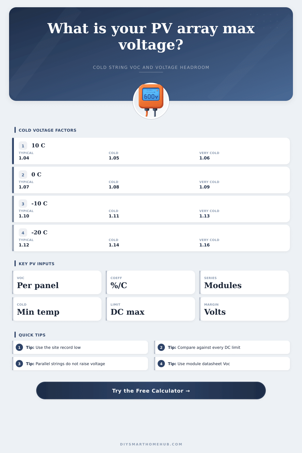
| Lowest Ambient | Approx Factor at -0.24%/°C | Approx Factor at -0.28%/°C | Approx Factor at -0.32%/°C |
|---|---|---|---|
| 10°C / 50°F | 1.036 | 1.042 | 1.048 |
| 0°C / 32°F | 1.060 | 1.070 | 1.080 |
| -10°C / 14°F | 1.084 | 1.098 | 1.112 |
| -20°C / -4°F | 1.108 | 1.126 | 1.144 |
| -30°C / -22°F | 1.132 | 1.154 | 1.176 |
| -40°C / -40°F | 1.156 | 1.182 | 1.208 |
The calculator uses the coefficient you enter. This table is a quick check for common crystalline silicon module coefficients.
| Equipment Class | Typical Max PV Input | Best Fit | Voltage Design Note |
|---|---|---|---|
| Portable solar generator input | 60 to 150 Vdc | 1 to 3 modules in series | Cold Voc often limits series count before power does. |
| Residential charge controller | 150 to 250 Vdc | 2 to 5 modules in series | Confirm both PV input voltage and MPPT operating window. |
| Hybrid inverter, small string | 450 to 600 Vdc | 6 to 12 modules in series | Often constrained by 600 Vdc residential equipment ratings. |
| Commercial string inverter | 1000 Vdc | 14 to 20 modules in series | Check every combiner, fuse holder, disconnect, and connector. |
| Ground-mount high-voltage inverter | 1500 Vdc | 22 to 30 modules in series | Use only equipment listed for the full voltage class. |
| Module Type | Typical Voc Range | Typical Voc Coefficient | String Sizing Impact |
|---|---|---|---|
| Compact 12 V nominal module | 21 to 25 V | -0.28% to -0.34%/°C | Good for low-voltage controllers, but series count rises quickly. |
| 60-cell or 120 half-cell module | 38 to 43 V | -0.26% to -0.31%/°C | Common in residential strings and mid-voltage battery systems. |
| 72-cell or 144 half-cell module | 45 to 51 V | -0.24% to -0.30%/°C | Higher Voc reduces allowed series count on 600 Vdc equipment. |
| Large-format bifacial module | 49 to 56 V | -0.22% to -0.28%/°C | Often best paired with 1000 Vdc or 1500 Vdc equipment. |
| High-voltage thin film module | 90 to 230 V | Technology-specific | Use manufacturer instructions instead of crystalline assumptions. |
| Project Scenario | Example Array | Primary Voltage Check | Secondary Check |
|---|---|---|---|
| Portable backup input | 2 x 200 W modules, 2S1P | Stay under 100 to 150 Vdc input | Confirm connector and adapter voltage rating. |
| Detached shed battery system | 6 x 370 W modules, 3S2P | Cold Voc under 150 Vdc controller | Check MPPT starting voltage on warm mornings. |
| Garage hybrid inverter | 8 x 370 W modules, 8S1P | Cold Voc under 450 Vdc input | Check DC disconnect voltage rating. |
| Residential roof string | 20 x 400 W modules, 10S2P | Cold Voc under 600 Vdc | Confirm optimizers, rapid shutdown devices, and inverter. |
| Commercial rooftop string | 108 x 550 W modules, 18S6P | Cold Voc under 1000 Vdc | Confirm combiner and fuse holder voltage class. |
| Utility style ground mount | 240 x 585 W modules, 24S10P | Cold Voc under 1500 Vdc | Confirm all DC gear is listed for 1500 Vdc service. |
Solar panels produces electricity using silicon. The voltage that solar panels produce, however, change based off the temperature of the environments in which the solar panels is installed. Many individuals looks at the open circuit voltage (Voc) that is published on the solar panel manufacturers datasheet.
The Voc, however, is measured at a standard temperature of 25 degrees Celsius. Because the temperature of the environment in which the solar panels are install may be different than 25 degrees Celsius, the voltage that the solar panels produce will change based upon the change in the temperature of the environments. If the temperature of the environment decrease, the voltage that is produced by the solar panel increase.
Check Solar Panel Voltage in Cold Weather
The increase in voltage of the solar panel, though, could cause the voltage produced by the solar panel to exceed the maximum voltage limits of the inverter or a charge controller that is installed in the solar power system. Should the voltage limit of the inverter or the charge controller be exceeded, the inverter or the charge controller may fail in hardware. To avoid the possibility that the inverter or the charge controller will fail in hardware, it is important to calculate the voltage that will be produced by the solar panels in cold weather environment.
In order to calculate the voltage that will be produced by the solar panels in cold weather environments, one can determine the temperature coefficient for the solar panel from the manufacturers datasheet. The temperature coefficient is a percentage that represent the increase in voltage of the solar panel for each degree that the temperature of the solar panel drop from 25 degrees Celsius. The peak voltage of the solar panel can be calculated by determining the open circuit voltage of the solar panel, the number of solar panel in the solar array, and the record low temperature in the location in which the solar panel will be install.
After the manufacturer specifications has been calculated for the peak voltage for the solar panel, that voltage can be compared to the voltage limit of the inverter or the charge controller to determine the voltage headroom for the system. The voltage headroom is the difference in voltage between the maximum voltage that the solar panel array can produce and the voltage limit of the inverter or the charge controller. Should the voltage headroom be too small to allow for cold weather conditions, the inverter or the charge controller may be exceeded in voltage.
Thus, a voltage headroom of at least five percent are recommended. In addition to determining the voltage headroom for the solar power system, it is also important to ensure that each component of the DC path of the system can handle the peak voltage of the solar array. The DC path include the solar panel, the fuses, the DC disconnect, and the inverter.
Should any component of the DC path have a lower voltage limit than the peak voltage of the solar array, that component may fail. Thus, the installer should inspect each component of the DC path to ensure that each can handle the peak voltage of the solar array. Another important distinction are between the open circuit voltage (Voc) of the solar panel and the maximum power voltage (Vmp) of the panel.
The Vmp is the voltage that the solar panel produces when the solar panel is actively produce a current. The Vmp is used to ensure that the inverter operate within its maximum power point (Mppt) operating window. The Voc, in contrast, is the voltage that the solar panel produces when it is not actively pushing any current, such as immediately after turning on the solar array.
Because the Voc is always higher than the Vmp, you should use the Voc for any calculation to determine the voltage of the solar array. Finally, it is also important to understand the voltage and current of the solar array. By adding solar panels in series to the solar array, the voltage of the solar array will increase.
Thus, care should be taken to ensure that the voltage of the solar array does not rise to levels that may exceed the voltage limits of the inverter or the charge controller. Additionally, by adding solar strings in parallel to the solar array, the current of the solar array will increase, but the voltage will not. Thus, if the voltage of the solar array is too high for the equipment that is to be used to convert the DC voltage of the solar array into DC or AC electrical power, strings of solar panels can be added in parallel with the current solar panel strings rather than adding additional panels in series.
Overall, then, you can manage each component of the solar array to ensure that the total energy harvested from the solar array is maximized while keeping the voltage within a safe limit.