Main Bonding Jumper Size Calculator
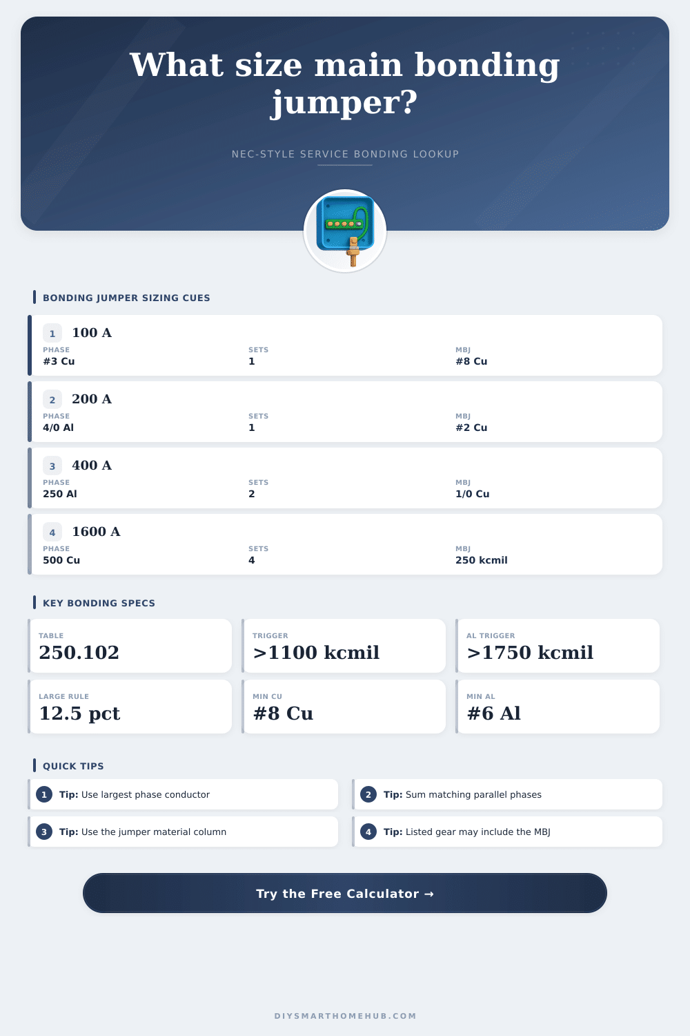
Size a service main bonding jumper from the largest ungrounded conductor, conductor material, parallel sets, and NEC-style Table 250.102(C)(1) logic.
This table is reproduced as a practical calculator reference for grounded conductors and bonding jumpers on AC systems. Always apply the adopted code and equipment listing for the actual installation.
| Copper largest ungrounded conductor | Aluminum largest ungrounded conductor | Copper bonding jumper | Aluminum bonding jumper | Calculator action |
|---|
| Conductor size | Circular mil area | Approx. square mm | Use in this calculator |
|---|
| Preset | Service rating | Largest ungrounded conductor | Parallel sets | Copper jumper result | Rule |
|---|
| Fault-current condition | What it means for bonding | Calculator response | Field check |
|---|
The main bonding jumper are the conductor that connect the grounded conductor to the equipment grounding systems. When electricians open the main disconnect on a service, they are look for the main bonding jumper. A main bonding jumper has a specific job to be performed, which is to carry the fault currents from a ground fault to allow the overcurrent device to trip.
Additionally, the main bonding jumper cannot become hot from the fault current, nor it should create a voltage difference between conductors that are otherwise touch by individuals. Because of these requirements of the main bonding jumper, the size of the main bonding jumper is a critical factor for the installation of the electrical service equipment. The size of the main bonding jumper is determined by the size of the largest ungrounded phase conductor.
Main Bonding Jumper: Its Job and How to Size It
If the service utilize parallel runs of conductors, the electrician should calculate the equivalent area of those phases. The total area of the ungrounded phase conductor is the size of the main bonding jumper. For instanse, if there are multiple phase conductor in a leg of the electrical service, their circular mil area should be add together.
There is a threshold to the size of the main bonding jumper, since the sizing table for main bond jumpers cannot be indefinitely expanded. If the equivalent area of the phase conductors are 1,100,000 circular mils or more in copper, or if the equivalent area of the phase conductors is 1,750,000 circular mils or more in aluminum, a different sizing rule for main bonding jumpers is applied. For these larger electrical services, the main bonding jumper must be at least one-eighth of the total area of the phase conductors.
This rule ensure that in very large services, the main bonding jumper is still large enough to handle the fault current without overheat. The main bonding jumper size can also be affect by the type of main bonding jumper that is to be utilized. If the service utilize aluminum phase conductors but utilize copper main bonding jumper, the main bonding jumper sizing tables provides separate values for copper main bonding jumpers, and separate values for aluminum main bonding jumpers.
Additionally, while the calculation will provide a size for the main bonding jumper, such a calculated value is only a planning number, and the authority having jurisdiction over the electrical installation must still confirm the main bonding jumper size. Finally, the main bonding jumper size must also comply with the equipment listing. The available fault current of the service and the clearing time for the overcurrent device that protect the service are also necessary piece of information in determining the size of the main bonding jumper.
The available fault current can help to determine the stress that will be placed on the main bonding jumper. If the main bonding jumper is in the moderate or high range of fault current stress, the enclosure, lugs, and bracing for the service equipment must also be rated to those same fault current. The main bonding jumper is not the only component of the service that must be able to withstand the energy of a ground fault.
Many individuals make mistake regarding the main bonding jumper. One of the most common mistake is treating the main bonding jumper as if it is the same as an equipment grounding conductor. The main bonding jumper is sized different than the equipment grounding conductor, and the equipment grounding conductor does not have the same rules applied to it outside of the service equipment.
For instance, many individuals may reach for the green insulated wire that is in close proximity to the service conductor as the main bonding jumper. This is not to be assumed of any equipment grounding conductor is a main bonding jumper. The main bonding jumper is the single point that maintain the same electrical potential between the grounded conductor and any metal enclosure in the service equipment.
Additionally, if sized correctly, it will allow the overcurrent device to clear the fault before damage occur to the service equipment. If sized incorrectly, the main bonding jumper may create a point of failure in the service equipment. Thus, while calculators may be used to find the starting size of the main bonding jumper, the final decision regarding size must also take into account the equipment listing, the adopted edition of the code, and the specific condition of the electrical service installation.