Junction Box Fill Calculator
Calculate required cubic inches for a junction box from insulated conductors, device yokes, grounding conductors, internal clamps, fixture supports, selected wire gauge allowance, and listed box volume.
📌Box fill presets
⚙Fill inputs
🔍Live fill insights
📊Box and wire spec comparison grid
📋Wire gauge volume allowances
| Conductor size | Volume allowance | One yoke allowance | Ground bundle allowance |
|---|---|---|---|
| 18 AWG | 1.50 in³ per conductor | 3.00 in³ | 1.50 in³ total |
| 16 AWG | 1.75 in³ per conductor | 3.50 in³ | 1.75 in³ total |
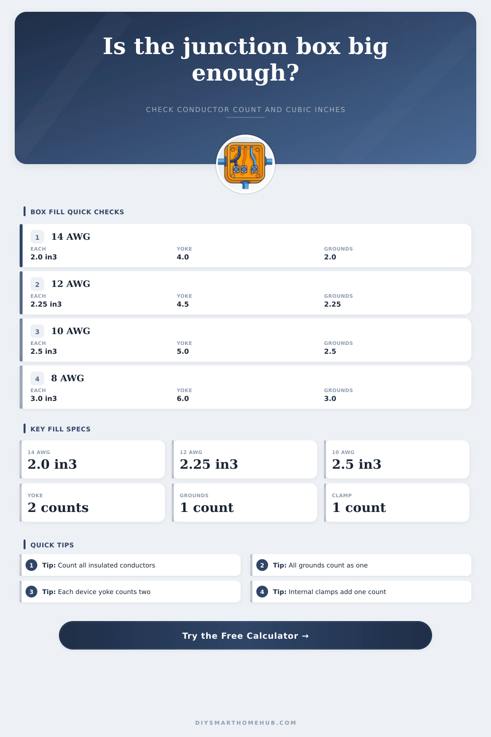
| 14 AWG | 2.00 in³ per conductor | 4.00 in³ | 2.00 in³ total |
| 12 AWG | 2.25 in³ per conductor | 4.50 in³ | 2.25 in³ total |
| 10 AWG | 2.50 in³ per conductor | 5.00 in³ | 2.50 in³ total |
| 8 AWG | 3.00 in³ per conductor | 6.00 in³ | 3.00 in³ total |
| 6 AWG | 5.00 in³ per conductor | 10.00 in³ | 5.00 in³ total |
🗃Common box volume reference
| Box style | Reference volume | Best fit in this calculator | Watch point |
|---|---|---|---|
| Shallow 1-gang old work | About 12.5 in³ | Very simple switch loops | Often fails with smart devices or feed-through splices. |
| Standard 1-gang nail-on | About 18.0 in³ | Basic switch or receptacle work | Internal clamps and 12 AWG conductors tighten capacity quickly. |
| Deep 1-gang device box | About 21.0 in³ | One device plus more conductors | Device depth still affects usable working space. |
| 4 in square, 1.5 in deep | About 22.5 in³ | Splice junctions and covers | Raised covers may have their own volume markings. |
| 4 in square, 2.125 in deep | About 30.3 in³ | Dense splices or larger gauges | Use actual stamped marking for final volume. |
| Two-gang deep box | About 42.0 in³ | Smart controls and two yokes | Multiple devices add two counts each. |
🧮Conductor count rules used
| Item in box | Count used | Formula effect | Calculator input |
|---|---|---|---|
| Insulated conductor entering or passing through | One per conductor | Count x gauge volume allowance | Insulated conductor count |
| Device yoke or strap | Two per yoke | Yokes x 2 x gauge volume allowance | Device yokes or straps |
| Equipment grounding conductors | One total allowance | 1 x gauge volume if any grounds exist | Equipment grounding conductors |
| Internal cable clamp | One total allowance | 1 x gauge volume if internal clamps exist | Internal cable clamps |
| Fixture stud or hickey | One total allowance | 1 x gauge volume if supports exist | Fixture studs or support fittings |
| Short pigtail starting and ending in same box | Zero added allowance | Excluded from fill total | Do not add to insulated count |
📐Preset comparison table
| Scenario | Gauge | Counted conductors | Box volume cue |
|---|---|---|---|
| Smart switch neutral | 14 AWG | 8 code-count conductors | 18 in³ is close; deep box helps working room. |
| Garage GFCI feed-through | 12 AWG | 9 code-count conductors | 21 in³ or larger is usually the useful comparison. |
| Ceiling fan control box | 14 AWG | 9 code-count conductors | Support fittings can add one allowance. |
| Two-gang smart controls | 14 AWG | 14 code-count conductors | Two yokes add four conductor allowances before splices. |
| 10 AWG control junction | 10 AWG | 8 code-count conductors | Larger wire needs more cubic inches per count. |
💡Box fill notes
A junction box fill calculator will allow you to determine whether a junction box have enough room to contain all of the conductors and devices that are to be placed within that junction box. The reason for using a junction box fill calculator is that junction box must meet certain requirements within teh code regarding the volume of the junction box. Should the junction box be too small for the amount of conductors and devices that is to be contained within it, the junction box will fail the inspection; thus, it is essential to use such a calculator to ensure that the junction box that is to be used is large enough to contain those conductors and devices.
The first step in calculating the appropriate size of the junction box is to determine the size of the largest conductor that will be contained within the junction box. The size of the largest conductor within the box will determine the cubic-inch allowance that will be made for all of the other items that is to be contained within the junction box. For instance, a conductor that is sized at 12 AWG will require more cubic inch of space than a conductor that is sized at 14 AWG.
How to Use a Junction Box Fill Calculator
Additionally, you should use the size of the largest conductor within the junction box for the calculations of the size of the junction box; the code require that the size of the largest conductor is used to calculate the allowances for all other items within that junction box. The next step is to count the number of insulated wire that will be contained within the junction box. Count the number of hot wires, neutral wires, travelers, and switch legs.
Do not count the number of short pigtails; however, do count the number of device yokes separately. Each device yoke count as two conductors; thus, a single smart switch will take up the same amount of volume within the junction box as two individual wires. Additionally, you will count the grounding conductors as a single group.
Only one allowance will be provided for all grounding conductors within the junction box. Additionally, you should count the number of internal clamps and fixture supports. Each of these items will take up one cubic inch of the junction box.
These rules exist for these items within the junction box because all grounding conductors share a common path; thus, there is no need to count each individual grounding conductor. Additionally, these rules exist for the internal clamps and fixture supports because these items will occupy a certain amount of space within the junction box. Finally, the last step in calculating the size of the junction box is to provide the listed volume of the junction box.
Every junction box has a marked volume in cubic inches; this marked volume is the dimension that should be referenced for determining whether or not the junction box will pass code requirements. In most cases, it is essential to use the listed volume of the junction box rather than making an assumption regarding it’s volume based off its outer dimensions. Incorrectly assuming the volume of a junction box based upon its outer dimensions is a common mistake that will result in code failures.
Instead, using a junction box fill calculator will allow you to not only select the common sizes of junction boxes that will be used in your installation, but also to ensure that each junction box that is selected have a volume that is greater than the total volume of the required items within it. Common mistakes in performing these calculations include under-counting the number of device yokes, or incorrectly treating each grounding conductor within the junction box as an individual allowance. If you make these mistakes in the counting of the volume of the junction box, the volume of the junction box that is calculated will be too small to contain all of the items that will be placed into it.
Therefore, an undersized junction box may pass the inspection; however, the junction box will be too small to contain the items that are to be placed into the box. Additionally, one of the other common mistakes is in the mixing of wire gauges. If you mix wire gauges, the largest gauge should be used for calculating the volume of the junction box.
Even if a junction box passes the minimum requirement for code, the box may be difficult to install into the fixture. To prevent this difficulty in installation, it is common to add a certain percentage of headroom to the calculated volume requirements for the junction box. This percentage provides headroom for the electrician to work within the junction box.
Additionally, this percentage will also provide headroom for any future electrical installation within the junction box. Although not required by code, this percentage will help an electrician to determine if the installation will be easy to complete. The goal of the use of a junction box fill calculator is for the electrician to be able to choose a junction box that will be able to contain all of the conductors and devices that are to be installed into it.
The chosen junction box should contain enough room for the electrician to make their electrical connections. Thus, using a junction box fill calculator will allow the electrician to make their choice of junction box visible to the other members of the construction team prior to placing the cover onto the junction box.