Smart Switch Load Check Calculator
Compare a smart switch or relay module against a connected load using watts, amps, voltage, power factor, inrush multiplier, derating, and per-channel limits.
📌Real Load Presets
⚡Switch and Load Inputs
Switch Load Results
⚙Switch and Load Spec Comparison Grid
📊Reference Tables
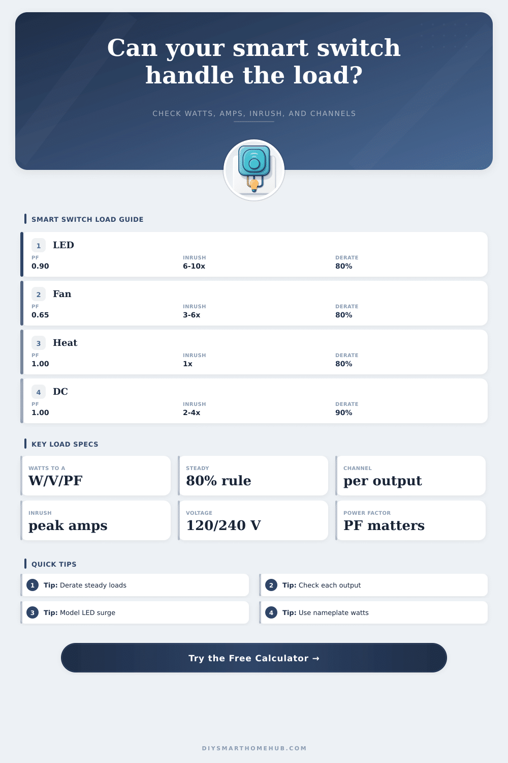
| Load Class | Power Factor Used | Typical Inrush Range | Why It Matters |
|---|---|---|---|
| LED driver or smart bulb group | 0.85 to 0.95 | 6x to 10x running current | Low watts can still stress relay contacts when many drivers energize together. |
| Incandescent or halogen lighting | 1.00 | 1.2x to 1.8x running current | Simple resistive math, but cold filaments create a brief turn-on bump. |
| Resistive heater or heat lamp | 1.00 | 1x to 1.2x running current | Steady current and continuous-load derating are the main constraints. |
| Small AC fan motor | 0.60 to 0.75 | 3x to 6x running current | Motor ratings and relay contact type matter more than watts alone. |
| Pump motor | 0.80 to 0.90 | 5x to 7x running current | Locked-rotor and restart current can exceed a general lighting switch rating. |
| Low-voltage DC output | 1.00 | 2x to 4x running current | Channel current rises quickly at 12 V or 24 V because voltage is low. |
| Switch or Relay Rating | Common Rated Load | Derated Continuous Load | Best Fit |
|---|---|---|---|
| 5 A smart dimmer or small relay | 600 W at 120 V resistive equivalent | 4 A using an 80% rule | LED lighting groups and small non-motor loads within the lamp rating. |
| 10 A smart wall switch | 1,200 W at 120 V resistive equivalent | 8 A using an 80% rule | General lighting, bathroom fans, and moderate mixed loads. |
| 15 A plug-in module | 1,800 W at 120 V resistive equivalent | 12 A using an 80% rule | Appliance-style resistive loads where the module is rated for them. |
| 16 A DIN relay module | 3,840 W at 240 V resistive equivalent | 12.8 A using an 80% rule | Panel-mounted control of larger resistive or properly rated motor loads. |
| 2 A low-voltage channel | 48 W at 24 V DC | 1.6 A using an 80% rule | Small LED strips, valves, relays, and actuator outputs. |
| Running Watts | 120 V at PF 1.00 | 120 V at PF 0.70 | 24 V DC at PF 1.00 |
|---|---|---|---|
| 60 W | 0.50 A | 0.71 A | 2.50 A |
| 120 W | 1.00 A | 1.43 A | 5.00 A |
| 300 W | 2.50 A | 3.57 A | 12.50 A |
| 600 W | 5.00 A | 7.14 A | 25.00 A |
| 1,500 W | 12.50 A | 17.86 A | 62.50 A |
| Preset Scenario | Voltage and Load | Switch Rating | Primary Check |
|---|---|---|---|
| Kitchen LED cans | 120 V, 180 W LED driver load | 5 A lighting-rated dimmer | Low running current but high LED turn-on multiplier. |
| Bathroom fan | 120 V, 85 W small motor | 10 A wall switch | Power factor and motor inrush raise the amp check. |
| Plug-in heater | 120 V, 1,500 W resistive load | 15 A module | Continuous derating is the limiting factor. |
| Dual irrigation valves | 24 V, 36 W transformer load | 5 A per relay channel | Per-channel current is checked after channel splitting. |
| Small pool pump | 240 V, 750 W pump motor | 20 A motor-rated relay | Motor inrush margin is more important than steady watts. |
✅Load Check Tips
This calculator is a planning check for load matching. Confirm the exact device datasheet, load category, enclosure temperature, protection device, and local electrical rules before using any smart switch or relay.
When you use a smart switch to turn on lights, the smart switch use a relay to provide electricity to the load. For the installation of a smart switch to be successful, you must match the electrical load that the smart switch is to be controlled by to the smart switch relay. Many people dont perform this critical task of matching the load to the relay, which can result in the smart switch failing early or the smart switch refusing to power the electrical fixture.
Comparing the number on the nameplate of the electrical load with the ratings on the smart switch is a simple step that you must perform to ensure that the smart switch will be able to handle the load. Each electrical load draw current in a different way. For example, LED drivers often have low wattage ratings, but draw several time that wattage when first switched on.
Match a Smart Switch to the Electrical Load
Exhaust fans often have low wattage ratings for there running loads, but the fans place stress on the relay due to their low power factor and long startup surge. Resistive heaters have a steady electrical current, and have a power factor that is near one, causing them to create heat within the smart switch. Relays are not rated for the wattage of the load, but for the different type of current that each type of load draws.
The calculator provided here can perform the mathematical calculations necesary to determine if the smart switch can handle the electrical load. After entering the voltage of the circuit, the total running watts of the load, the load class, and the switch ratings, the calculator will convert the running watts into running amps, using the power factor of the load class. The derating percentage that is entered will determine how many amps the relay can carry continuously.
Furthermore, the calculator will divide the total running amps by the number of active channels of the smart switch. Finally, the calculator will multiply the running current by the inrush factor to determine the peak of the inrush current, which you will compare with the switch ratings to ensure that the load match the smart switch. The power factor is a critical element to the calculations of whether a smart switch can handle an electrical load.
A load with a low power factor will draw more current than if it had a high power factor. The load class selector allow for the power factor to be selected appropriately for the load. Derating relays is important for ensuring that relays do not overheat.
For example, a relay that can carry 15 amps for short periods of time may overheat if it is required to carry 12 amps for long periods of time. The derating percentage allow for the smart switch to account for warm environments and long periods of operation. Furthermore, derating percentages that are set to a more conservative number than the switch specifications allow for the possibility that the switch will be installed in an insulated box.
Inrush current is another factor in the calculations. For example, if the inrush current of an appliance is too high, the relay contacts may weld together. You can enter the inrush current into the calculator and the calculator will model it to determine whether or not it will match the smart switch.
Each room typically has different type of electrical loads. For example, there may be both exhaust fans and LED lights. In this case, you can enter the total watts into the calculator along with the load class.
Furthermore, there are different load profile that can be tested in the calculator, and you can compare each load with the smart switch to determine if it can handle each type of load. Multi-channel relay modules allow for different channels to have their own on/off switches. You can divide the total amps drawn by the load by the number of active channels to determine whether the current of each channel is within the limit of that channel alone.
This prevents relay failure caused by each channel being near its limit. Temperature has an effect on the relay, but the calculator does not measure it. For example, relays may pass the calculations if they are in a cool environment in the house, but may overheat and fail if they are in a warm enclosure such as teh kitchen hood.
In this case, you can increase the derating percentage so as to allow the relay to dissipate more heat. The most common failure of a smart switch is due to the installer failing to account for the different specification of the switch. For example, the installer may fail to account for the impact of the power factor, the inrush current, and the individual limit of the channels within the smart switch.
Each of these specification are forced to be accounted for in the calculations that this calculator performs. The goal is for the smart switch to match to the electrical load so that the relay will last for a long time. By ensuring that the smart switch accounts for the running current, the per-channel current, and the inrush current, the relay will not fail.
Furthermore, by recognizing these common issue early in the installation process, you could of changed the smart switch and its components before the installation is complete.