Smart Hallway Motion Spacing Calculator
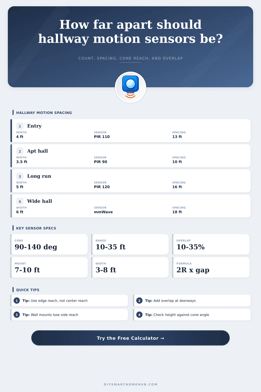
Plan hallway motion sensor count and center-to-center spacing from hallway length, width, sensor cone angle, rated range, overlap target, mounting height, and detection height.
📌Real hallway presets
📏Hallway and sensor inputs
Coverage sketch
Choose a preset or enter hallway dimensions to preview the spacing plan.
Hallway spacing results
Full calculation breakdown
💡Motion sensor/spec comparison grid
These cards summarize common hallway motion sensing profiles. Use manufacturer data when it differs from the defaults.
📚Reference tables
Sensor profile comparison table
Use this table to compare the default angle, reliable range, and best-fit hallway use for each calculator profile.
| Sensor profile | Default angle | Reliable range | Mount assumption | Best hallway use |
|---|---|---|---|---|
| Ceiling PIR, 90 degree cone | 90° | 18 ft / 5.5 m | Ceiling centerline | Narrow apartment entries and short halls |
| Ceiling PIR, 110 degree cone | 110° | 22 ft / 6.7 m | Ceiling centerline | General bedroom halls and corridors |
| Wide PIR, 120 degree cone | 120° | 28 ft / 8.5 m | Ceiling centerline | Longer straight runs with doorways |
| Very wide PIR, 150 degree cone | 150° | 24 ft / 7.3 m | Ceiling centerline | Wide gallery halls where edges matter |
| Ceiling mmWave presence sensor | 140° | 32 ft / 9.8 m | Ceiling centerline | Long halls needing presence-style coverage |
| Side-wall PIR hallway sensor | 100° | 20 ft / 6.1 m | Wall or door frame | Garage entries and retrofit wall boxes |
| Narrow beam or door transition sensor | 35° | 35 ft / 10.7 m | End wall or beam aim | Door transitions, stair landings, low ceilings |
Hallway preset results table
The table is calculated from the same count, spacing, cone angle, range, overlap, and mounting height formulas used by the form.
| Preset | Hall dimensions | Sensor profile | Overlap | Calculated plan |
|---|
Cone angle and height reach table
For a centered ceiling sensor, cone reach at target height is limited by mounting height and half-angle before rated range is applied.
| Mount to target drop | 90 degree cone | 110 degree cone | 120 degree cone | 140 degree cone |
|---|---|---|---|---|
| 4 ft / 1.2 m | 4.0 ft span half | 5.7 ft span half | 6.9 ft span half | 11.0 ft span half |
| 5 ft / 1.5 m | 5.0 ft span half | 7.1 ft span half | 8.7 ft span half | 13.7 ft span half |
| 6 ft / 1.8 m | 6.0 ft span half | 8.6 ft span half | 10.4 ft span half | 16.5 ft span half |
| 7 ft / 2.1 m | 7.0 ft span half | 10.0 ft span half | 12.1 ft span half | 19.2 ft span half |
| 8 ft / 2.4 m | 8.0 ft span half | 11.4 ft span half | 13.9 ft span half | 22.0 ft span half |
Formula reference table
The spacing model treats a hallway sensor footprint as a width-corrected cone. The result is conservative for cross traffic and doorway breaks.
| Formula step | Expression | Why it matters | When it limits spacing |
|---|---|---|---|
| Vertical drop | Mount height - target height | Defines where the cone intersects a moving person | Low ceilings or high target height reduce reach |
| Cone floor radius | Drop x tan(angle / 2) | Turns the datasheet angle into a horizontal radius | Narrow angle sensors shrink quickly |
| Range radius | sqrt(range² - drop²) | Prevents the cone from exceeding reliable sensor range | Short-range sensors or high mounting heights |
| Edge half-reach | sqrt(radius² - lateral offset²) | Ensures the far hallway edge is still inside coverage | Wide halls and wall-mounted sensors |
| Max sensor spacing | 2 x edge reach x (1 - overlap) | Subtracts the overlap target from the raw cone span | Higher overlap means more sensors |
| Sensor count | ceil(usable length / spacing) + 1 | Rounds up so the entire straight run is covered | Long halls or short corrected spacing |
✅Hallway spacing tips
Placing motion sensor in a hallway require planning because the placement of the motion sensors determines whether the light will turn on when a person enters the hallway. Several factor must be considered when placing motion sensors in a hallway, such as the distance between the motion sensors, the angle of the motion sensors’ detection cones, and the mounting height of the motion sensors. If these factors isnt considered when placing motion sensors in a hallway, there will be blind spots in the hallway.
The width of the hallway, the mounting height of the motion sensors, and the angle of the motion sensors’ detection cones all plays important roles in determining the performance of the motion sensors. Motion sensors is usually designed for use in open rooms. However, hallways are not considered open rooms because hallways have wall on either end of the hallway that may interfere with the motion sensors’ detection cones.
How to Place Motion Sensors in a Hallway
The walls of the hallway will cause the motion sensors’ detection cones to hit the walls of the hallway, thus reducing the reliably detection distance of the motion sensor. If you place motion sensors based only on the range at which they can detect motion, hallways will have a problem in that there will be gaps in the detection of motion by the motion sensors. These gaps in coverage exist in the areas where individuals will walk through the hallway.
The geometry of the motion sensor’s detection cone can also impact the placement of the motion sensors. The detection cone of motion sensors placed on the ceiling of a hallway will become wider the further the motion sensor is from the floor in which the individuals will walk. The wider the hallway, the more farther apart the motion sensors need to be placed on the ceiling.
The mounting height of the motion sensors also affects the performance of those motion sensors. The higher that you mount the motion sensors on the walls or ceiling of the hallway, the farther that the detection cone of the motion sensors will have to travel to reach the individuals that is walking through the hallway. For instance, if a motion sensor is mounted to an eight-foot ceiling, the horizontal radius of the motion sensor’s detection cone will be different at the height of a person’s waist than if the motion sensor are mounted to a ceiling at seven feet.
Because of these differences, the mounting height of the motion sensors will affect the total number of motion sensors that will be necessary to illuminate the hallway. Another important factor to consider when placing motion sensors in a hallway is the necessary overlap between the detection cones of the motion sensors. Many people may believe that if the detection cones of the motion sensors touch at the edge of the hallway, the coverage will be continuous.
However, there must be some overlap between the detection cones of the motion sensors. If there is too little overlap between the detection cones of the motion sensors, a person that walks slow through the hallway may pass through a dead band in which no motion sensor will turn on the lights. If there is too much overlap between the detection cones of the motion sensors, there will be extra cost for purchasing additional motion sensors for the hallway.
The motion sensor calculator will provide mathematical results based on the length of the hallway, the width of the hallway, the angle of the motion sensor detection cone, the reliable range of the motion sensor, the mounting height of the motion sensors, the height at which the motion sensors will detect motion, the desired overlap between the detection cones of the motion sensors, and the distance between the end of the hallway and the detection range of the motion sensors. Based on these measurement, the calculator will adjust the radius of the motion sensor’s detection cone to ensure that the parameter for the hallway are accounted for. The motion sensor calculator will also provide a quality score for the suggested placement of motion sensors that inform the individuals whether the coverage of the motion sensors’ detection cones for the width of the hallway is marginal.
The motion sensor calculator will not provide perfect coverage for the hallway; however, it can aid in avoiding the placement error of motion sensors that are based only upon the measurements provided in the datasheet of the motion sensors. In real hallways, there are additional complications beyond those accounted for by the motion sensor calculator. Motion sensors that are placed in hallways may encounter complications created by doors that open into the hallway, turns in the hallway, and low beam in the hallway.
In cases in which the temperature in the hallway changes, such as near an exterior door, passive infrared motion sensors may have issues in detecting motion. However, motion sensors that use millimeter waves are more reliable in detecting motion, even though they are more expensive. To ignore any traffic created by pets in the hallway, the target height of the motion sensors must be lowered.
However, if you lower the target height of the motion sensors, the radius of the motion sensor’s detection cone will shrink. A smaller detection cone radius mean that motion sensors will need to be placed closer to each other in the hallway. The type of motion sensors that will be used will also impact where they will be placed in the hallway.
For instance, narrow-beam motion sensors will cover more distance than wide-angle ceiling motion sensors. However, narrow-beam motion sensors will not cover the edge of a wide hallway. In contrast, wide-angle ceiling motion sensors will cover the edges of a hallway better but will reach a shorter distance down the hallway.
Additionally, motion sensors that are mounted on the walls of the hallway will not be able to effectively detect individuals that walk on the far side of the passage because the lateral offset of the motion sensors will cause their detection cone to not reach those individuals. The motion sensor calculator can be used to change the profile of the motion sensors to determine the impact of each type of motion sensor on the distance at which motion sensors should be placed in the hallway. Before placing motion sensors in a hallway, it is recommended to measure the hallway twice and to place and test one motion sensor in the hallway.
After placing the first motion sensor at the calculated distance between motion sensors, the hallway can be walked through to determine where the motion sensor will detect motion. Depending on the placement of the motion sensor, the next motion sensor may need to be moved closer together to the first motion sensor or the motion sensor with a wider detection cone may be selected. The purpose of placing motion sensors in a hallway is to ensure that when an individual enters the hallway, the motion sensors will turn on the light for that hallway and that the motion sensors will provide the lights for the next motion sensor to detect the individual entering the hallway.
If all the factors are accounted for when placing motion sensors in a hallway, the motion sensors will perform as they are intended to perform. Thus, if the motion sensors perform in the way that they are programmed to, the individual will not have to think of the motion sensors; they will perform their function as they are intended to do.