💨 Ductwork Pressure Drop Calculator
Calculate pressure drop (in. WC), velocity, and friction rate for smart HVAC duct balancing
✅ Pressure Drop Results
| Duct Type | Friction Rate | Velocity Range | Application |
|---|---|---|---|
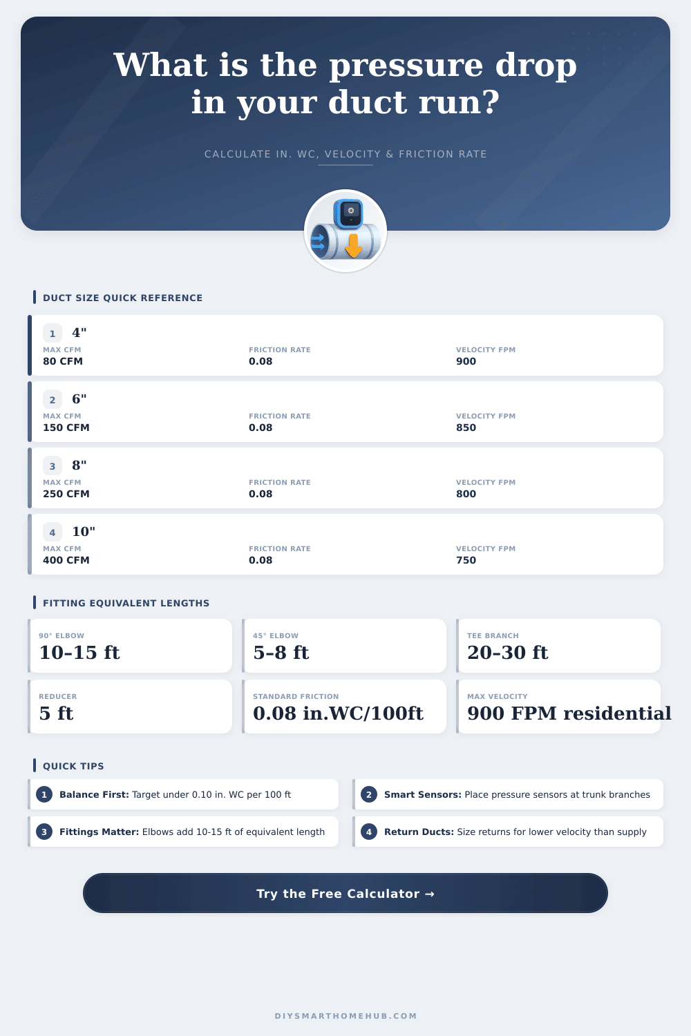
| Supply Trunk | 0.06 – 0.08 in.WC/100ft | 600 – 900 FPM | Main supply from air handler |
| Branch Duct | 0.08 – 0.10 in.WC/100ft | 400 – 700 FPM | Room supply branches |
| Return Duct | 0.06 – 0.08 in.WC/100ft | 400 – 600 FPM | Return air pathways |
| Exhaust Duct | 0.08 – 0.12 in.WC/100ft | 500 – 800 FPM | Bath, kitchen exhaust fans |
| Flex Duct | 0.10 – 0.15 in.WC/100ft | 300 – 600 FPM | Final connections, short runs |
| Fitting Type | Equivalent Length (ft) | Notes |
|---|---|---|
| 90° Elbow (radius) | 10 – 15 ft | Use 12 ft for standard calc; square elbows up to 20 ft |
| 45° Elbow | 5 – 8 ft | Use 6 ft for standard calc |
| Tee (branch takeoff) | 20 – 30 ft | Use 25 ft; straight-through tees use 5 ft |
| Reducer / Transition | 5 ft | Gradual transitions lower loss |
| Register / Grille | 15 – 25 ft | Varies by type; check manufacturer data |
| Flex Duct Connector | 3 – 5 ft | Per connection, keep runs fully extended |
When air moves through ductwork system, it meets resistance, which causes a drop of the total pressure. To ensure enough airflow, the fan or the air handling unit must beat those losses. Basically, that is the main idea behind ductwork pressure drop.
The ductwork pressure drop is made up of three parts. There are frictional losses at the walls of the ducts, dynamic losses at the fittings, and other losses caused by gear like hoods, filters, louvers or dampers. These physical factors create pressure drops, that quickly add up.
Why Air Pressure Drops in Ductwork
In systems with low velocity, the pressure drop is very little, usually around 1 Pa per metre of straight ductwork. In one particular system from round steel, the value was 1.3 Pa per metre. Various factors affect the total pressure, including the form of the ducts, its fittings and the kinetic energy.
When the ducts are smaller, the air moves more quickly, which causes higher pressure drop.
In flex duct pressure drop, the drop is almost double as big as in metallic tubes. That is an important spot when you choose the material. Usually, ductwork is designed so that the total external pressure drop stays under 200 Pa (which is less than 1 inch of water column).
Even so, in Canada, some designs reach 1 inch of static pressure.
For branch ductwork, a target of less than 0.08 inch per 100 feet usually suffices. For duct mains above occupied areas, that transports more than 8,000 CFM, a speed of 1,600 feet each minute is common. Many companies use “ductulator” with a rate of 0.1 inch per 100 feet for the supply and 0.08 inch for the return.
Even small losses at the fittings can affect the whole. In systems with many curves or sharp bends, the cumulative impact becomes big. A round elbow with radius of 1.5 times the diameter has a loss coefficient of about 0.15 regarding the velocity pressure.
A square elbow can have a coefficient up to 1.2. Losses at the tees of branch ductwork can be huge. Some fittings even have two different tables of losses, depending on if the airflow diverges or converges.
Longer and broader ducts require more force from the fan to push the air, and corners create resistance, especially if there are no guides. But you must recall, that ductwork is made and installed by people, which costs money. Every inch of tube, every turn and every change of diameter creates resistance, that the system must beat.
Hence you usually make a list to find the pressure drop at every section of the network, marking the nodes and covering both the tubes and fittings.