DC Power Voltage Drop Calculator
Check one-way cable distance, AWG size, conductor material, and load current for 5V, 12V, 24V, and 48V DC smart home power runs.
| Wire Gauge | Copper Ohms / 1000 ft | Approx Circular Mils | Best DC Use |
|---|---|---|---|
| 24 AWG | 25.67 | 404 | Data cable pair checks |
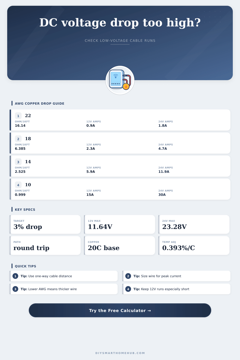
| 22 AWG | 16.14 | 642 | Short sensor pigtails |
| 20 AWG | 10.15 | 1,022 | Small control wiring |
| 18 AWG | 6.385 | 1,624 | Cameras and short LED runs |
| 16 AWG | 4.016 | 2,583 | Medium 12V or 24V loads |
| 14 AWG | 2.525 | 4,107 | Longer LED and relay runs |
| 12 AWG | 1.588 | 6,530 | High-current low-voltage trunk |
| 10 AWG | 0.999 | 10,380 | Long 12V distribution |
| 8 AWG | 0.6282 | 16,510 | Large DC bus extensions |
| 6 AWG | 0.3951 | 26,240 | Very high current DC feeds |
| Device Type | Typical Voltage | Typical Current | Voltage Drop Target |
|---|---|---|---|
| Addressable LED strip section | 5V or 12V | 2A to 8A | 1% to 3% |
| Analog LED tape zone | 12V or 24V | 1A to 6A | 3% to 5% |
| Low-voltage camera | 12V | 0.4A to 1.5A | 3% to 5% |
| Door strike or lock | 12V or 24V | 0.5A to 2A | 5% peak check |
| Relay or I/O panel | 12V or 24V | 0.2A to 2A | 3% recommended |
| Passive PoE DC feed | 24V or 48V | 0.2A to 1A | 3% to 5% |
| Conductor Option | Resistance Factor | Temperature Rule | Calculation Note |
|---|---|---|---|
| Copper | 1.00x | 20°C base | Standard AWG reference values |
| Tinned copper | 1.02x | Same copper coefficient | Slightly higher practical resistance |
| Aluminum | 1.64x | Higher thermal sensitivity | Needs larger conductor for same drop |
| Copper-clad aluminum | 1.55x | Varies by construction | Use conservative voltage margin |
| Parallel equal pairs | Divide resistance | Equal length only | Two equal pairs roughly halve drop |
| Project Scenario | Example Run | Better Starting Gauge | Reason To Check Drop |
|---|---|---|---|
| Short cabinet LED zone | 12V, 2A, 10 ft | 18 AWG | Small voltage headroom |
| Long under-shelf LED tape | 24V, 4A, 35 ft | 14 AWG | Brightness can fade at far end |
| Outdoor camera feed | 12V, 1A, 60 ft | 16 AWG | Night IR raises current draw |
| Garage controller trunk | 24V, 3A, 80 ft | 12 AWG | Long cable loop resistance |
| Rack cooling fan bank | 12V, 4A, 12 ft | 16 AWG | Startup current margin |
When calculating an voltage drop for a DC circuit with low voltage, such as for security camera, LED strips, or smart lock, the voltage that reaches the device will be lower than the voltage provided by the power supply. The voltage loss that occur within the cable is due to the heating of the wire. The longer the cable and the higher the current passing through the wire, the more higher the voltage loss.
Using a DC power voltage drop calculator allow a technician to determine the correct size of wire for the circuit before installing the cable. To calculate the voltage drop, the DC power voltage drop calculator requires that the technician input several parameter into the calculator. The technician must enter the first parameter, the source voltage of the power supply.
How to Use a DC Voltage Drop Calculator to Choose the Right Wire
The technician must enter the second parameter, the load current of the device. The third parameter is the distance of the circuit, which the calculator will double because the current must travel through two conductor to reach the device. The fourth parameter is the wire gauge, which will affect the resistance of the circuit.
The fifth parameter is the material of the wire. The sixth parameter is the temperature of the circuit. Finally, the technician must enter an allowed percentage of voltage drop.
The DC power voltage drop calculator will provide three answer to the technician. The first answer is the actual voltage at the device. If the voltage is too low, then the device may not function as it should.
The second answer is the percentage of voltage loss due to resistance of the wire. Many installations will allow no more than 3% loss of voltage. The third answer is the recommended gauge for the wire to allow for the voltage drop that was entered into the calculator.
It is important to calculate the voltage drop along the cable before installing the low-voltage system. Devices such as security cameras might work during the day but fail to work at night due to low voltage. The same is true for LED strips that might look good during the day but have poor lumen at night.
It is also more economical to calculate the voltage drop and select the appropriate wire size when installing the circuit rather than correcting the problem after installation. When calculating the voltage drop of a DC circuit, use the peak current of the device rather than the average current. Some device use more current when starting up than when in operation.
Using the peak current as the current will allow for a voltage drop that ensures that the device will not reset or go into sleep mode. Also, remember that the voltage drop is not one-way; the length of the cable must be doubled in the voltage drop calculator to include the return path of the circuit. In some instances, it is advantageous to install two parallel conductors of the same gauge rather than using a single conductor of a thicker gauge.
If the user uses two 18 gauge conductor in parallel, the resistance will be halved, which will result in a voltage drop that is half of that of a single conductor. The voltage drop calculator will account for this by dividing the resistance of the wire according to the number of parallel conductor. The material of the wire and the operating temperature of the circuit will also affect the voltage drop within the wire.
Using aluminum rather than copper reduces the cost of installation but requires a larger wire gauge for the same current. The current will also have a voltage drop if the wire is exposed to high temperature; the wire will have more resistance when hot than when in a cooler location within the house. The voltage drop calculator will account for the material and the temperature of the circuit.
Technicians must decide whether the voltage drop calculator will account for the estimated or actual temperature of the wire during installation of the circuit. Technicians who calculate the voltage drop along the cable make some common mistake are made by technicians. One of the most common is using the available wire gauge rather than the recommended wire gauge calculated by the voltage drop calculator.
Another mistake is using the average current instead of the peak current of the device. Using the average current will cause the voltage drop along the cable to be higher than should be permitted, which will result in failures of the device when it demand the higher current when starting up. Although the voltage drop calculator eliminates the need for the technician to perform the manual calculation, the voltage drop calculator does not account for all condition that might occur in a circuit.
Technicians should always refer to the device datasheet and use a multimeter to measure the voltage drop along the cable. The goal of calculating the voltage drop along the cable is to ensure that the voltage at the device is the same as the source voltage so that the device operates in the same way as when it was manufactured. Using a DC power voltage drop calculator allows a technician to easily install low-voltage device with ease.