DC Power Supply Filter Capacitor Calculator
Estimate bulk capacitance, capacitor ripple current, voltage rating, ESR heating, and hold-up time for rectified DC supplies.
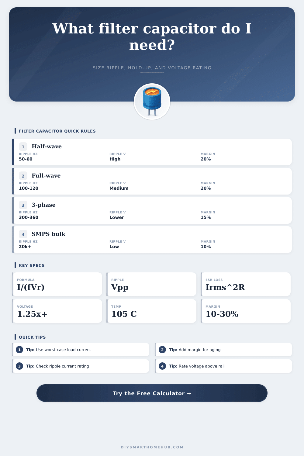
| Topology | Ripple frequency formula | 50 Hz source | 60 Hz source | Use when |
|---|---|---|---|---|
| Half-wave rectifier | f ripple = 1 × line frequency | 50 Hz | 60 Hz | Very small, low-current supplies where ripple can be large |
| Full-wave bridge | f ripple = 2 × line frequency | 100 Hz | 120 Hz | Most single-phase transformer DC supplies |
| Full-wave center-tap | f ripple = 2 × line frequency | 100 Hz | 120 Hz | Dual-diode transformer secondaries with a center tap |
| 3-phase 6-pulse rectifier | f ripple = 6 × line frequency | 300 Hz | 360 Hz | Industrial DC rails and cabinet supplies |
| Switching bulk stage | f ripple = switching or charging frequency | Application set | Application set | SMPS bulk caps, boost stages, and pulsed DC links |
| DC rail type | Typical Vpp target | Typical load range | Capacitor priority | Notes |
|---|---|---|---|---|
| 5 V microcontroller rail before regulator | 0.25 to 0.5 Vpp | 0.1 to 1.5 A | Low ESR plus local ceramics | Keep regulator dropout and WiFi burst current in mind |
| 12 V relay, lock, or camera rail | 0.5 to 1.5 Vpp | 0.5 to 4 A | Ripple-current rating | Loads may switch sharply, so add local bypassing near devices |
| 24 V actuator or DIN rail control | 1 to 2.5 Vpp | 1 to 8 A | Voltage rating and life | Cabinet heat makes 105°C electrolytics preferable |
| Audio or analog pre-regulator rail | 0.1 to 0.5 Vpp | 0.05 to 3 A | Low ripple and grounding layout | Hum-sensitive circuits need lower ripple than digital loads |
| Motor or solenoid DC link | 2 to 5 Vpp | 2 to 20 A | Surge current and ripple current | Transient suppression is separate from bulk capacitance sizing |
| Capacitor type | Useful capacitance range | ESR behavior | Best role in a DC supply | Design caution |
|---|---|---|---|---|
| Aluminum electrolytic, general purpose | 47 µF to 47,000 µF | Moderate | Bulk smoothing after 50/60 Hz rectifiers | Check ripple current and temperature life |
| Low-ESR aluminum electrolytic | 100 µF to 22,000 µF | Low | Higher-current rails and switching outputs | Parallel parts may be needed for ripple current |
| Polymer electrolytic | 22 µF to 2,200 µF | Very low | Fast load steps and compact low-voltage rails | Voltage ratings are usually lower than wet electrolytics |
| Film capacitor | 0.1 µF to 100 µF | Very low | High pulse current and snubber support | Large values become physically bulky |
| Ceramic MLCC | 0.01 µF to 100 µF | Extremely low | High-frequency bypass close to ICs | DC bias can greatly reduce effective capacitance |
| Example rail | Input assumptions | Minimum capacitance | Practical bank | Voltage rating check |
|---|---|---|---|---|
| 5 V ESP32 hub | 0.6 A, 120 Hz, 0.35 Vpp | 14,286 µF before margin | 18,000 to 22,000 µF | 10 V minimum, 16 V preferred |
| 12 V relay board | 1.6 A, 120 Hz, 1 Vpp | 13,333 µF before margin | 18,000 µF class | 16 V minimum, 25 V preferred |
| 24 V actuator bus | 3 A, 120 Hz, 1.8 Vpp | 13,889 µF before margin | 18,000 to 22,000 µF | 35 V minimum, 50 V preferred |
| 48 V PoE lab rail | 1.5 A, 120 Hz, 2 Vpp | 6,250 µF before margin | 8,200 to 10,000 µF | 63 V minimum |
| 3-phase 24 V cabinet | 6 A, 360 Hz, 1.2 Vpp | 13,889 µF before margin | 18,000 to 22,000 µF | 35 V minimum, 50 V preferred |
When you are choosing an filter capacitor for your DC power supply, you must consider how the capacitor will impact the stability of your circuit. The value of the filter capacitor will determine whether your voltage rail remain flat when your load spike to high values. The value of your capacitor will also determine whether your voltage drop too low to cause issue for your circuits (such as resetting a microcontroller).
These calculations can all be performed with the calculator; simply enter the parameter for your circuit, and the calculator will remove the need for manually calculating these formulas. Most power supplies employ a bridge rectifier. A bridge rectifier will cause the filter capacitor to experience two input pulses during each cycle of the AC power line frequency.
How to Choose a Filter Capacitor for a DC Power Supply
Thus, the ripple frequency is doubled, and the capacitance requirement is halved in comparison to a single-phase half-wave rectifier. The calculator perform these calculations automatically. The capacitance requirement for a half-wave rectifier running at 60 Hz will be roughly twice that of a full-wave bridge rectifier.
Thus, the ripple currents of the capacitor will need to double as well. The load current of the circuit is another variable that many people choose to underappreciate. For the load current, you should enter the continuous worst-case value of the current into the calculator.
Your capacitor will discharge at the worst-case current value, because this is the most rapid rate at which the capacitor will be discharged. Thus, if your rail is rated at 2 A continuously, but can spike to 3 A during certain event (such as motor start or Wi-Fi data bursts), you must use the worst-case 3 A value in the capacitor calculation. Otherwise, you may need to choose a larger capacitor to account for these spikes, or you may experience sag of the rail at these times.
The hold-up calculation can show how many millisecond of droop you can create by adding bulk capacitance to your supply; this can help you to decide between adding bulk capacitance or adjusting your transformer. Because the capacitor will experience the peak voltage of the AC power line (and any overshoot from electrical transients), the voltage rating of the capacitor must be higher than the nominal DC voltage of your rail. Furthermore, electrolytic capacitors tend to lose their lifetime if they are operate near their voltage ratings, especially at elevated temperatures.
Thus, the calculator will provide a voltage class suggestion once you enter your desired rail voltage and a chosen voltage margin. This margin ensure that the capacitor is never operated near its voltage limits, which will extend the life of the capacitor and provide headroom for the capacitor to age. Another factor to consider is the resistance of the capacitor and its ripple current.
The calculator will automatically calculate the RMS ripple current based on the load and topology of your power supply. A capacitor may have a low ESR, and may have a relatively high capacitance value, but if the ripple current is too high for the capacitor, the capacitor will overheat. The calculator provides a reference table that list typical ripple limits for various types of rails.
For example, many circuits use a 5 V microcontroller which require ripples of less than 0.5 V; an actuator bus at 24 V, on the other hand, can tolerate more ripple. Capacitors have a temperature rating. In most cases, an electrolytic capacitor rated to 105 °C is a better component to use than one that is only rated to 85 °C. While the 85 °C capacitor may cost a little more, the higher temperature rating will extend the life of the capacitor, especially in a closed enclosure that may reach 60 °C internally.
While the calculator will not calculate the temperature of the capacitor, the voltage margin can be used to add bulk capacitance to the power supply to compensate for the expected reduction of capacitance at elevated temperatures. This extra bulk capacitance prevent the power supply from sagging under load after the capacitors age. The hold-up time of your power supply is another consideration.
If your power supply must continue to provide power during an interruption in the incoming power lines, the hold-up time is important. Additionally, if you have a DC-DC regulator on your rail, there will be a minimum input voltage that the regulator requires to remain in regulation. The calculator will tell you in milliseconds how long your capacitor bank will hold the rail above the headroom value that you enter.
This can help you to determine if you should use one large capacitor vs. Several smaller capacitor in parallel. Capacitors in parallel has a lower total ESR. Engineers and technicians make many mistake in selecting a capacitor.
Some of these mistakes include choosing the capacitor to handle only the average current of the load rather than the worst-case/peak current; ignoring the difference between half-wave and full-wave ripple frequency; and choosing a capacitor voltage rating that is the same as the nominal rail voltage of the DC power supply. The calculator forces the user to consider each of these factor before ordering capacitors for their circuits. For switching regulator topologies, the same concepts apply.
The ripple frequency will jump from the line frequency to the switching frequency; hence, a higher frequency mean that the required ESR will be lower than the linear topology. Additionally, due to the fast edge in switching regulators, the ripple current often increases with the switching regulator; thus, the ripple current must be accounted for in the calculations. The calculator will account for both linear and switching topology calculations once the user has selected the appropriate topology.
Finally, there is a trade-off in selecting the value of the capacitor. On one side is cost, size, temperature life, and ripple voltage. The tables surrounding this calculation allow the designer to make a decision based on the actual circuit for which the capacitor will be purchased.
For unusual circuit, the parameters that will be used with the calculator will allow for the engineering judgment of the designer to be incorporated into the capacitor selection process.