DC Voltage Drop Calculator
Estimate voltage loss in two-wire DC circuits using system voltage, one-way cable length, load current, conductor material, wire size, and your target drop limit.
Calculation breakdown
| Wire size | Copper resistance | Round-trip at 50 ft | Example drop at 5 A |
|---|---|---|---|
| 18 AWG | 6.385 ohm / 1000 ft | 0.6385 ohm | 3.19 V |
| 16 AWG | 4.016 ohm / 1000 ft | 0.4016 ohm | 2.01 V |
| 14 AWG | 2.525 ohm / 1000 ft | 0.2525 ohm | 1.26 V |
| 12 AWG | 1.588 ohm / 1000 ft | 0.1588 ohm | 0.79 V |
| 10 AWG | 0.999 ohm / 1000 ft | 0.0999 ohm | 0.50 V |
| 8 AWG | 0.6282 ohm / 1000 ft | 0.0628 ohm | 0.31 V |
| 6 AWG | 0.3951 ohm / 1000 ft | 0.0395 ohm | 0.20 V |
| 4 AWG | 0.2485 ohm / 1000 ft | 0.0249 ohm | 0.12 V |
| Cross-section | Copper resistance | Round-trip at 20 m | Example drop at 10 A |
|---|---|---|---|
| 1.5 mm² | 12.1 ohm / km | 0.484 ohm | 4.84 V |
| 2.5 mm² | 7.41 ohm / km | 0.296 ohm | 2.96 V |
| 4 mm² | 4.61 ohm / km | 0.184 ohm | 1.84 V |
| 6 mm² | 3.08 ohm / km | 0.123 ohm | 1.23 V |
| 10 mm² | 1.83 ohm / km | 0.073 ohm | 0.73 V |
| 16 mm² | 1.15 ohm / km | 0.046 ohm | 0.46 V |
| 25 mm² | 0.727 ohm / km | 0.029 ohm | 0.29 V |
| 35 mm² | 0.524 ohm / km | 0.021 ohm | 0.21 V |
| DC circuit type | Typical target | Why it matters | Calculator setting |
|---|---|---|---|
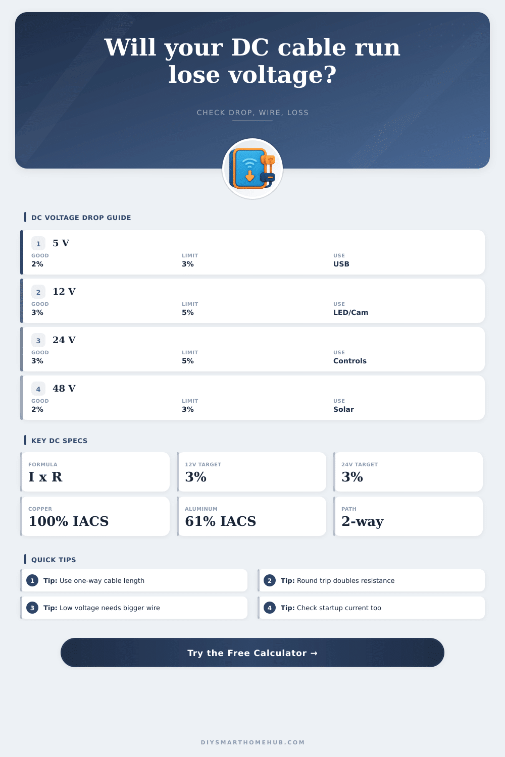
| 5 V USB sensors or logic | 2% to 3% | Small voltage loss is large relative to 5 V | 2% |
| 12 V LED lighting | 3% to 5% | Brightness and color can vary with voltage | 3% or 5% |
| 12 V cameras and routers | 3% to 5% | Adapters may reset near their low-voltage limit | 3% |
| 24 V controls and relays | 3% to 5% | Higher voltage tolerates longer runs better | 3% or 5% |
| 48 V battery and solar DC | 2% to 3% | Loss becomes heat at higher current | 2% or 3% |
| Device or circuit | Common voltage | Typical current | Voltage-drop sensitivity |
|---|---|---|---|
| USB sensor extension | 5 V DC | 0.1 A to 1 A | Very high; keep short or use thicker cable |
| LED strip branch | 12 V or 24 V DC | 1 A to 8 A | High; long strips show dim far ends |
| Security camera power | 12 V DC | 0.5 A to 2 A | Medium; IR night mode can raise current |
| Access control lock | 12 V or 24 V DC | 0.5 A to 5 A | High; release coils need reliable pull-in voltage |
| Control cabinet bus | 24 V DC | 0.2 A to 10 A | Medium; derate for shared loads |
| Battery inverter cable | 12 V to 48 V DC | 25 A and up | Very high; power loss rises with current squared |
When you run a direct current circuit over a distance, the voltage at the end of the circuit are often not the same as the voltage at the power source. This difference in voltage is known as voltage drop, and voltage drop occur because voltage drop turns into heat within the wire. For low voltage circuits, voltage drop is a major concern because a small amount of voltage drop have a large percentage drop in the total circuit voltage.
For instance, a one volt loss on a 12 volt circuit is an eight percent loss in voltage. An eight percent loss in voltage may cause LED strips to dim in brightness or camera to reset to a previous setting. Voltage drop occurs in a circuit due to the resistance in the conductors in the circuit.
What Is Voltage Drop and How to Calculate It
Thus, resistance in the conductors is the cause of the voltage drop in a circuit. In order to calculate the voltage drop in a circuit, it is first necessary to measure the distance from the power source to the load. Additionally, it is important to remember that the current has to travel out on one conductor from the power source to the load, but it also has to return on the other conductor from the load back to the power source.
Thus, the distance that the current travels is actualy twice the distance from the power source to the load. In order to calculate the resistance in the conductors, you must double the distance from the power source to the load. If the one way distance is used in the calculation of the resistance, the calculated value will not account for the return trip of the current.
Current is another major factor in voltage drop. Voltage drop increase with an increase in current. Voltage drop scales directly with amperage.
Thus, an increase in amperage will result in an increase in voltage drop. It is important to use the highest current for a device rather than the steady state current for the device. For instance, devices like motors or solenoid locks often draw the highest current when they are initially starting up rather than when they are running normally.
Thus, if you only use the steady state current, the circuit may not provide enough voltage to start the device. The materials from which the conductors of a circuit are formed will impact the amount of resistance in the circuit. For instance, copper is a common material for electrical conductors, but materials like aluminum or copper clad aluminum have higher resistance than copper.
Thus, if you use aluminum or copper clad aluminum, there will be more voltage drop than if copper is used. Additionally, tinned copper has a different resistance than bare copper. People often use tinned copper in outdoor settings or marine environment in which exposure to moisture could cause the bare copper conductor to corrode.
A voltage drop calculator will show the impact of using different conductor materials on the resistance in the circuit. Using parallel pairs of conductors can reduce the resistance in a circuit. For instance, if you run two identical conductors side by side with each end of the conductors connected together, the resistance in the circuit will reduce to half of the resistance of one conductor.
Thus, using multiple conductors in a circuit will reduce the total resistance of the circuit. However, using multiple conductors requires more copper than using a single conductor of larger diameter. The amount of voltage drop that is permitted in a circuit depends upon the requirements of the devices in the circuit.
For instance, circuits that contain sensitive electronics may require that the voltage drop is low, such as no more than two percent of the total voltage. Circuits that contain lights or other devices that are not as sensitive to voltage drop may permit as much as three percent of the total voltage to drop. Circuits that use higher voltages, such as battery or solar circuits, may permit as much as five percent of the total voltage to drop.
Thus, the load can select the voltage drop in a circuit based off the requirements for voltage. In addition to the variables that can be accounted for when calculating the voltage drop in a circuit, there are some additional variables that may impact the voltage drop within the circuit. For instance, all terminals, splices and connectors add to the resistance of the circuit.
Additionally, the temperature of the conductors will impact the resistance of the circuit. Higher temperatures will lead to higher resistance in the conductors. For instance, if the conductor is within a hot attic, the resistance of that wire will be higher than if it were calculated using standard methods.
Finally, the construction of the cable will impact the resistance of that cable. For instance, stranded wires have a different resistance than solid wires, especially when those wires is flexed or bent. Some common mistakes in voltage drop calculations include thinking that voltage drop is not related to the current in the circuit.
Additionally, another common mistake is to believe that a wire that is adequate for current delivery over a short distance will be adequate for long distance. People make these mistakes when they only considering one variable in the circuit, rather than considering the variables of current, length and resistance of the circuit. To avoid such mistakes, a voltage drop calculator will help ensure that all three of these variables is considered when calculating the appropriate size of the conductors in the circuit.
You should of used a calculator to be sure.