DC Power Supply Calculator
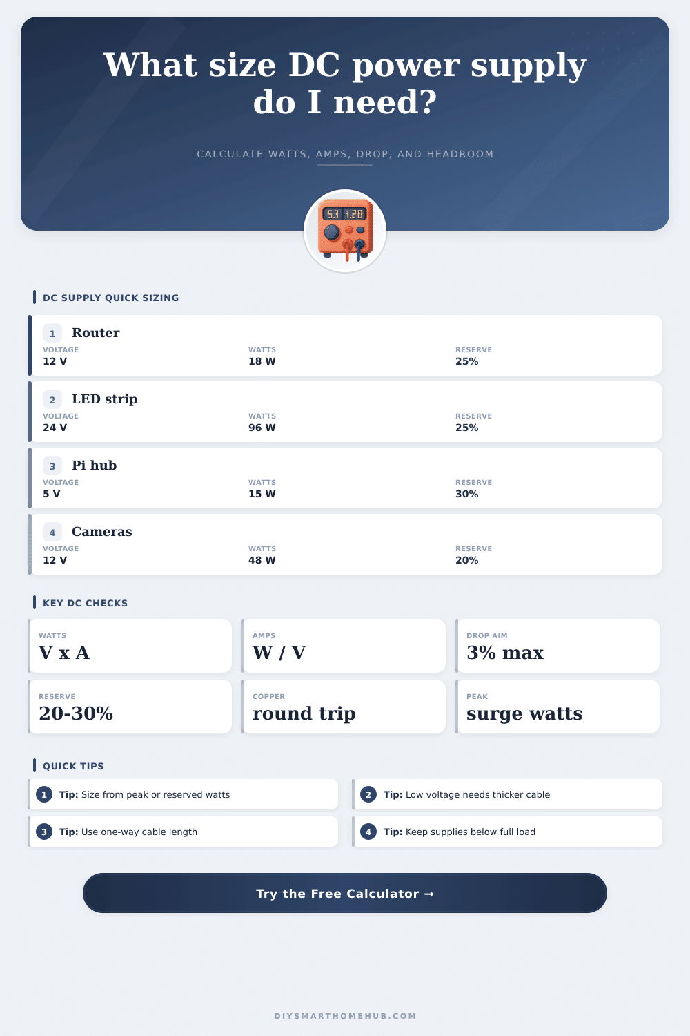
Size a regulated DC supply from load watts, startup surge, voltage, wire gauge, cable length, and reserve headroom.
⚙Real Low-Voltage Presets
📝Supply And Cable Inputs
Calculated DC Supply Size
Formula Breakdown
📊DC Sizing Formula Grid
💡Practical Sizing Notes
🔋Common DC Voltage Reference
| DC rail | Common smart-home loads | Drop sensitivity | Sizing note |
|---|---|---|---|
| 5 V | Raspberry Pi boards, microcontrollers, USB sensors | Very high; 0.25 V is already 5% | Use short leads or heavier cable for multi-amp loads |
| 9 V | Small audio interfaces, older electronics, some sensors | High; 0.27 V is 3% | Check polarity and adapter regulation before combining loads |
| 12 V | Cameras, routers, relay panels, locks, small LED strips | Moderate; 0.36 V is 3% | Most home DC bricks are 12 V constant-voltage supplies |
| 24 V | Longer LED strips, controls, automation panels | Lower; 0.72 V is 3% | Preferred for longer runs because current is half of 12 V at the same watts |
| 48 V | Telecom shelves, PoE-style distribution, DC UPS feeds | Low; 1.44 V is 3% | Use only with equipment rated for the higher DC voltage |
📏Copper Wire Resistance Reference
| Gauge | Ohms per 1000 ft | Approx mm2 | Best calculator use |
|---|---|---|---|
| 22 AWG | 16.14 ohm | 0.326 mm2 | Short low-current sensor pigtails |
| 20 AWG | 10.15 ohm | 0.518 mm2 | Light DC devices and short alarm cable runs |
| 18 AWG | 6.385 ohm | 0.823 mm2 | Common security, thermostat, and short LED wiring |
| 16 AWG | 4.016 ohm | 1.31 mm2 | Medium branches with several amps |
| 14 AWG | 2.525 ohm | 2.08 mm2 | Longer 12 V or 24 V lighting feeds |
| 12 AWG | 1.588 ohm | 3.31 mm2 | Higher current low-voltage trunks |
| 10 AWG | 0.999 ohm | 5.26 mm2 | Heavy DC feeder runs |
| 8 AWG | 0.628 ohm | 8.37 mm2 | Large trunk cables and high-current shelves |
🔌Typical DC Load Examples
| Load type | Typical voltage | Running watts | Peak sizing note |
|---|---|---|---|
| WiFi router or ONT | 12 V | 8 to 18 W | Use adapter label or measured draw plus 20% reserve |
| Raspberry Pi 4/5 hub | 5 V | 6 to 15 W | USB peripherals can push peak current much higher |
| 12 V IR camera | 12 V | 5 to 12 W | Night IR LEDs usually set the peak load |
| 24 V LED strip | 24 V | 9.6 to 19.2 W/m | Size from full brightness even if dimmed day to day |
| Relay board | 5 V or 12 V | 0.4 to 1 W per relay | Count the maximum relays energized at once |
| Electric strike | 12 V or 24 V | 6 to 18 W | Check fail-safe versus fail-secure duty cycle |
🏠Common Project Size Reference
| Scenario | Example load | Calculated supply | Cable focus |
|---|---|---|---|
| Router backup shelf | 24 W peak at 12 V | 30 W / 2.5 A | 18 AWG is usually fine for short shelves |
| Smart hub cluster | 20 W peak at 5 V | 25 W / 5 A | Keep 5 V cable short to avoid undervoltage |
| Four cameras | 48 W peak at 12 V | 60 W / 5 A | Long branches may need 16 AWG or local supplies |
| Cabinet LED run | 96 W peak at 24 V | 120 W / 5 A | 24 V reduces current versus 12 V strips |
| PoE feed shelf | 120 W peak at 48 V | 150 W / 3.13 A | 48 V tolerates longer feeder distance |
When you are choosing a DC power supply for your project, it is important to consider more than the watt that the device will draw when running. You must also consider the margin that the whole system require to account for the additional watts that the wiring draws during the startup of the powered devices. While many people will look at the sticker on the back of a router or a camera to determine the wattage of the device, those devices may run warm with the supply that you purchased, or the voltage at the device may be lower than expected.
These problems can arise from low voltage and long distances that the power travel. The calculator allows you to enter the load (in watts) of the devices that you will power, the length of the cable that will deliver the DC power to those devices, and the gauge of the wire that you will use. The load can be separated into the running watts that the devices continuously draw, as well as the peak watts that devices with infrared LEDs, for example, or devices with attached drive may draw for short period of time.
How to Choose the Right DC Power Supply
Power supplies that are sized for the running watts only can become warm when devices that draw high peak watts are switch on, but power supplies that are sized for the peak load will run cooler and for longer periods of time during normal operation. Another variable that must be consider when using this tool is the voltage drop. For instance, a drop of 0.5 volts at 5 volts is 10% of the power rail, which can cause a Raspberry Pi to reboot.
At 48 volts, a drop of 0.5 volts is less percentage of the total voltage. The voltage drop is shown in both volts and a percentage of the total voltage that is supply; this can help to determine whether the voltage drop with the given load and length of cable is adequate. If it is not adequate, then one option is to purchase thicker gauge wire to reduce the voltage drop, or to use a higher distribution voltage.
Another decision that you must make when using this tool is the headroom for the power supply. For instance, a power supply that is operating at 95% of its power rating will run hotter than a power supply at 50% of its power rating. Many installers will provide 20-30% headroom for electronic devices that is always on; the nameplate watts for the devices may be high under ideal conditions, but they may not be able to provide that much power for extended periods of time under normal conditions.
This headroom will be applied to the running load watts; the higher of the resulting number will be used as the minimum required size of the DC power supply. The length of the cable is entered into the calculator in one-way distance; the voltage drop formula will double the distance to provide an accurate calculation for the voltage at the devices; current travel out from the power supply to the devices, but also travels back to the power supply from the devices. Distance can be entered in feet or meters.
For a given length of cable, gauge, and load, the calculator will output the number of watts that is lost in the wire, as well as the voltage that reaches the devices. If the voltage that reaches the devices is too low, or if the watts lost in the wire are too high, then there are a few option for correcting the problem: shorten the length of the cable, raise the voltage of the power supply, or increase the size of the conductors. Many projects that employ DC power supplies will experience the issues discussed above.
For instance, a shelf that is used to house a router and an ONT may only draw 18 watts of power while the devices are running, but the power supply requirement may be 30 watts to supply that power to the devices while allowing for startup power for the devices. Four camera may appear to be a modest number of devices, but the power that the infrared LEDs on each of those cameras draw can double the running watts of each of those devices. These examples are just a few of the devices that will allow the designer to compare the easy number to the number that is actualy required for purchase.
Though this tool accounts for many of the factors that may contribute to power supply requirements, there are additional factor that are outside of the scope of this tool. For instance, power supplies that are within warm cabinets may not be able to deliver the same levels of power as a power supply within a cool basement. Additionally, electric strikes and solenoid locks may require high levels of power only while the locks are energized, so the average power draw will depend upon the frequency with which the doors is used.
Power meters can be used to measure the actual current draw of the loads, which will provide the most accurate reading of the actual power requirements for those devices. The tables that are provided on the page can be used to anchor the designer’s expectations of the DC power supply requirements. The voltage drop table demonstrate the effect of distance on 5 volt systems vs. 24 volt systems, for instance.
The wire gauge and resistance tables allow the designer to compare the resistance of wires of different gauge. These tables do not replace the power of a meter to measure actual load, but they can reduce the number of times that designers have to guess at the power requirements of their projects. The calculator allows designers to determine the true load of their devices, the distance that the power has to travel, and the headroom that they would like to allow for the power supply.
Given these answer, the designer can make an informed decision about which power supply to select from a short list of option.