Smart Camera Mounting Height Calculator
Calculate camera lens height from target distance, vertical field of view, downward pitch, face height, blind-zone limit, and bracket lens offset.
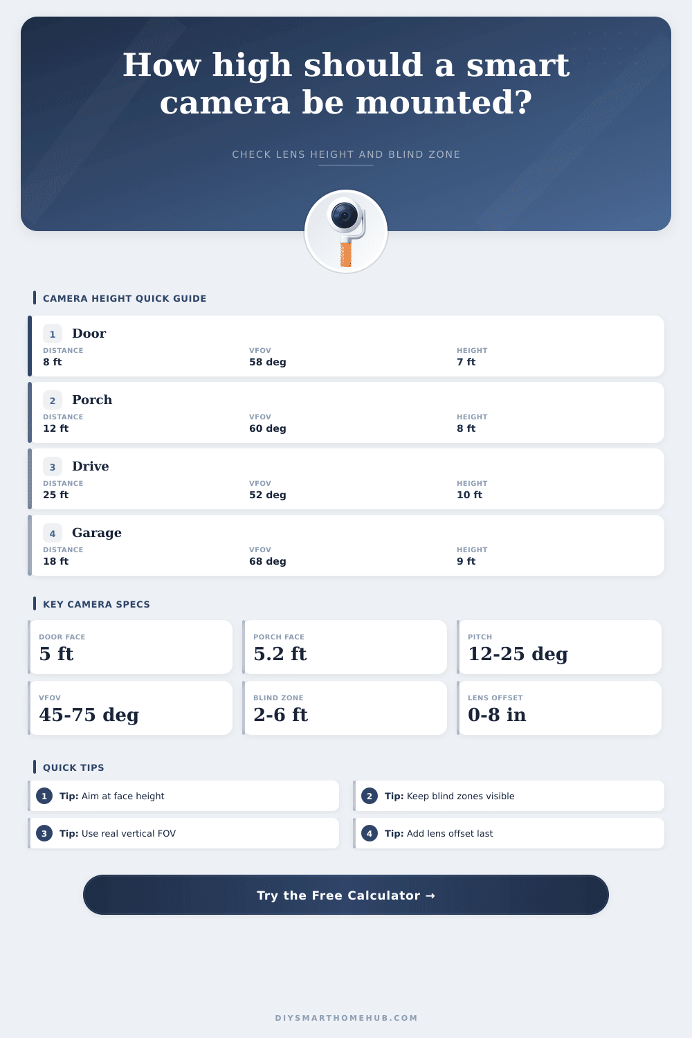
1.Camera placement presets
2.Mounting geometry
Enter camera geometry and calculate.
3.Camera/spec comparison grid
Tall frame with moderate blind-zone control near entries.
Longer reach, tighter vertical framing, pitch matters more.
Good for packages, patios, and close ground visibility.
Strong distance detail but needs careful aim height.
4.Reference tables
| Mounting scenario | Target distance | Common lens height | Target height | Primary tradeoff |
|---|---|---|---|---|
| Video doorbell | 4 to 8 ft | 4.0 to 5.0 ft | 4.5 to 5.2 ft face | Face angle versus package floor view |
| Front porch wall cam | 8 to 14 ft | 7.0 to 8.5 ft | 5.0 to 5.4 ft face | Small blind zone without looking too steep |
| Garage soffit driveway | 18 to 35 ft | 8.5 to 11.5 ft | 1.6 to 2.2 ft plate | Plate height is much lower than face height |
| Side yard path | 10 to 22 ft | 7.5 to 10.0 ft | 4.5 to 5.2 ft torso | Narrow walkways need lower blind zones |
| Indoor hallway | 10 to 20 ft | 7.0 to 8.0 ft | 4.8 to 5.2 ft face | Lower ceilings reduce pitch headroom |
| Vertical FOV profile | Typical camera type | At 10 ft distance | Best use |
|---|---|---|---|
| 35 to 45 deg | Optical zoom, narrow bullet | 6.3 to 8.3 ft vertical span | Driveway face or plate detail |
| 50 to 60 deg | Turret, doorbell, standard WiFi cam | 9.3 to 11.5 ft vertical span | Entry and porch monitoring |
| 65 to 75 deg | Floodlight, indoor pan-tilt | 12.7 to 15.3 ft vertical span | Packages, patios, rooms |
| 85 to 100 deg | Fisheye crop or ultra-wide | 18.3 to 23.8 ft vertical span | Close-range overview, less detail |
| Pitch angle | Optical-axis rise at 12 ft | Blind-zone effect | Use when |
|---|---|---|---|
| 8 deg | 1.7 ft above target | Longer blind zone | Camera is mounted low or target is far |
| 14 deg | 3.0 ft above target | Balanced entry view | Most porch and wall cameras |
| 22 deg | 4.8 ft above target | Shorter blind zone | Soffit mount with close walkway |
| 30 deg | 6.9 ft above target | Very short blind zone | High mount focused on packages or ground |
| Camera/spec profile | Vertical FOV used | Default lens offset | Recommended check |
|---|---|---|---|
| Doorbell tall portrait | 60 deg | 0 in | Confirm face is not above the top edge at close range |
| Bullet narrow | 45 deg | 2 in | Check that lower edge reaches the walkway soon enough |
| Floodlight wide | 68 deg | 7 in | Add bracket offset because lamps often sit above the lens |
| Indoor pan-tilt | 72 deg | -3 in | Use negative offset if shelf base is below lens center |
| Outdoor PTZ optical | 38 deg | 5 in | Narrow vertical FOV makes pitch-angle errors obvious |
5.Formula notes
| Formula | Calculator use | Meaning | Watch point |
|---|---|---|---|
| Lens height = face height + distance x tan(pitch) | Main lens result | Places the optical axis on the chosen target height | Use horizontal distance, not cable path length |
| Blind zone = lens height / tan(pitch + VFOV / 2) | Near ground result | Where the lower FOV edge first hits the ground | If this is too large, lower height or increase pitch |
| Top edge = lens height - distance x tan(pitch - VFOV / 2) | Target frame top | Highest visible point at the target distance | Negative edge angle points above level |
| Bottom edge = lens height - distance x tan(pitch + VFOV / 2) | Target frame bottom | Lowest visible point at the target distance | Low targets may fall below this line |
6.Mounting tips
This calculator estimates camera geometry only. Final mounting must respect the camera maker's weatherproofing, bracket loading, cable routing, and local electrical requirements.
When you installs a smart camera, the height of the smart camera is a critical factor in the installation process. The height of the smart camera will determine the coverage of the smart camera. If the smart camera is installed too low, there will be a blind zone where activity occurs within that zone.
If the smart camera is installed too high, the angle of the smart camera is too steeply for individuals faces to be within the smart camera’s frame. It is not a matter of guessing what the average height for a smart camera is. Instead, you should match the pitch and the vertical field of view of the smart camera with the distance and the height of the objects you want observe with the smart camera.
How to Set the Right Height and Angle for a Smart Camera
Many people starts with deciding on a mounting surface for the smart camera. One of the most common mounting surfaces for smart cameras is the soffit or the wall bracket. However, the position of the lens of the smart camera, rather than the mounting surface choice, influences the image quality of the smart camera.
Once people understands how the lens positioning relates to the subject of interest, the mounting surface choice will be apparent to them. The vertical field of view of a smart camera is a critical measurement for determining the lens placement. Many people will use the diagonal measurement of the smart camera instead of the vertical field of view.
For example, a smart camera may have a 120-degree diagonal field of view but a vertical field of view of only 60 degrees. The vertical field of view choice impact the aiming of the smart camera. A narrow vertical field of view means that the pitch of the smart camera makes a significant impact on the positioning of the lower edge of the smart camera’s frame.
A wide vertical field of view provides more freedom in the aiming of the smart camera but takes up more of the pixel of the smart camera’s screen. The pitch of the smart camera is another critical component of the smart camera placement. The pitch is the angle of the smart camera’s frame.
By adjusting the pitch of the smart camera, you can adjust the distance of the blind zone of the smart camera. Furthermore, if the pitch of the smart camera is increased, the far edge of the frame will be lowered. The lens height that is calculate for installation takes into account the target distance, vertical field of view, and the height of the target.
Another calculation to determine the final pitch of the smart camera is the addition of the bracket offset to the lens height. The blind zone of a smart camera is the area in front of the smart camera that the smart camera will not cover. Many people feel that raising the smart camera will increase the smart camera’s field of view.
However, the height of the smart camera will only move the lower edge of the smart camera’s frame away from the smart camera. If the blind zone is too large for the smart camera’s field of view, there is three options to fix this issue: increasing the pitch of the smart camera, moving the smart camera closer to the blind zone, or installing another smart camera to increase the coverage of the blind zone. Face framing for a smart camera is another important aspect of installing a smart camera.
If the optical axis of the smart camera is set to the height of the face of an individual that is to be observed by the smart camera, then the top and bottom edges of the frame will be even with the face. If the framing priority for the smart camera is set to the vehicle and the ground instead of the faces of the individuals that are to be observed, then the center line of the smart camera will shift in such a way that will cause the face to be near the top of the frame of the smart camera. The framing calculator show the vertical span of the smart camera and the margin of the smart camera around the target to determine if the subject will be large enough in the video of the smart camera once it has been compressed and cropped.
When installing a smart camera, there will be constraints that will be placed on the smart camera that were not accounted for in the mathematical calculations of where to position the lens. For example, the depth of the soffit may limit the placement of the screw for the bracket that mounts the smart camera. Another example is that the porch’s ceiling may be lower than the calculated height of the lens of the smart camera.
Another constraint may be forcing the motion of the smart camera a few inches from where it was calculated to be placed. These constraints may force a change in the height of the smart camera but will not change the calculations of where to place the lens. Some of the most common mistakes when installing a smart camera is to use the diagonal field of view measurement in place of the vertical field of view measurement.
The other common mistake is to use the pitch angle from the smart camera bracket instead of from the center of the lens of the smart camera. Both of these mistake will result in the placement of the lens of the smart camera being incorrect. To avoid this mistake, ensure that you read the vertical field of view specification and that you added the lens offset to the calculated height of the lens.
The reference tables shows different scenarios in which a smart camera can be mounted and the different vertical field of view, pitch, and distance specifications that will result. For instance, the video doorbell will have a lower lens height and a much gentler pitch than a smart camera that is mounted to a driveway. This is because the video doorbell is closer to the lens and lower in height.
The distance and vertical field of view specifications help to show why a driveway camera will need to have a more careful pitch of the lens to avoid a blind spot on the pavement. Over time, the smart camera will be exposed to the weather and will experience the movement of the installation location. For instance, the bracket that mounts the smart camera may shift over time due to the freeze-thaw cycle of the smart camera’s mounting location.
Additionally, the wood that makes up the structure of the mounting bracket may expand over time. Furthermore, the smart camera may drift in relation to true north by a few degrees after it has been mounted to the structure. To account for these shifts, inspect the video feed of the smart camera every few months to make necessary pitch adjustments to the lens of the smart camera.
The calculator that helps to determine the height for installation of the lens of the smart camera makes visible to the users the relationship between the distance, pitch, and vertical field of view of the smart camera before installation. Once individuals understands the relationship between these three elements, the placement of the smart camera on the mounting structure becomes a simple installation process. By following the calculations of the smart camera lens height, the brand of smart camera to be used, and the mounting structures available, the smart camera will be installed at the correct height and will capture the video that the smart camera owners need to see what occurs in the designated area.