Busbar Ampacity Calculator
Estimate flat copper or aluminum busbar ampacity from cross-section, temperature rise, enclosure cooling, plating, AC/DC current, and parallel bar sharing.
⚙Fast busbar presets
📏Busbar inputs
Busbar ampacity estimate
Results update after calculation.
🧱Busbar and material spec comparison
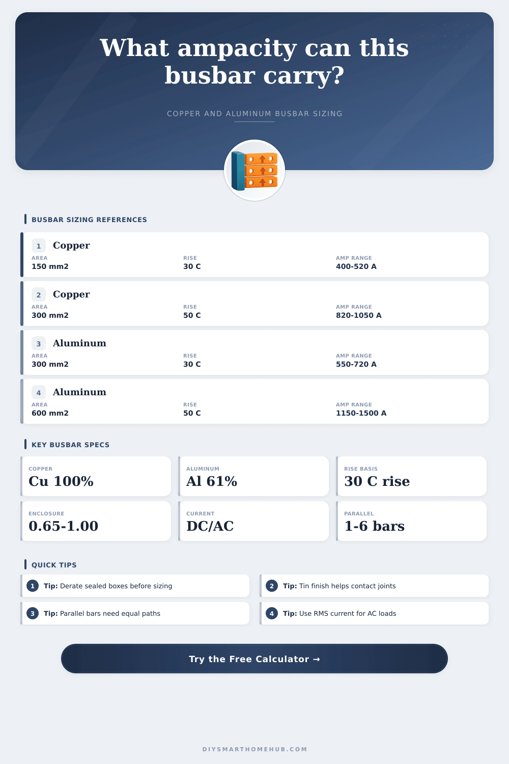
Copper and aluminum references appear after calculation.
The formula scales ampacity with the square root of rise.
Enclosed panels reduce natural convection around the bar.
Parallel bus runs are modeled below perfect linear sharing.
📊Reference tables
| Bar size | Copper open air | Aluminum open air | Typical use |
|---|---|---|---|
| 25 x 3 mm | About 230 to 290 A at 30 C rise | About 165 to 215 A at 30 C rise | Small DC links, compact branch bus, low energy panels |
| 30 x 5 mm | About 390 to 500 A at 30 C rise | About 280 to 365 A at 30 C rise | Battery combiners, small inverter cabinets, subfeeds |
| 50 x 6 mm | About 720 to 900 A at 30 C rise | About 520 to 670 A at 30 C rise | Main DC bus, EV cabinet bus, feeder distribution |
| 80 x 10 mm | About 1500 to 1900 A at 30 C rise | About 1080 to 1380 A at 30 C rise | High current switchgear, UPS, large power cabinets |
| Material profile | Relative conductivity | Resistivity at 20 C | Calculator effect |
|---|---|---|---|
| ETP copper bus | 100% IACS | 1.724e-8 ohm m | Highest common conductivity with compact cross-section |
| High conductivity copper | 101% IACS | 1.707e-8 ohm m | Small resistance improvement for dense assemblies |
| 6101 or 6061 aluminum bus | About 61% IACS | 2.826e-8 ohm m | Needs larger area for similar voltage drop and heat |
| 1350 aluminum bus | About 62% IACS | 2.783e-8 ohm m | Slightly better electrical grade aluminum reference |
| Condition | Factor range | Formula location | Planning note |
|---|---|---|---|
| Temperature rise | sqrt(rise / 30) | Base ampacity | Models the cooling increase from allowing a hotter bar surface |
| Enclosure cooling | 0.65 to 1.00 | Post thermal derate | Sealed boxes and crowded panels reduce natural convection |
| Plating or finish | 0.97 to 1.04 | Surface correction | Used as a small thermal and joint-quality correction |
| AC skin effect | 0.78 to 1.00 | Current-mode derate | Higher frequency and thicker bars reduce effective conducting area |
| Bars in parallel | Formula multiplier | Equal-path need | Design interpretation |
|---|---|---|---|
| 1 bar | 1.00 x single bar | Not applicable | Use for the baseline result and simple DC links |
| 2 bars | 2^0.92 = 1.89 | Matched length and joints | Good scaling when both bars share similar spacing and terminals |
| 3 to 4 bars | N^0.92 | Symmetric layout | Allows for unequal current sharing and proximity heating |
| 5 to 6 bars | N^0.90 cap | Very careful layout | Use detailed thermal validation for compact high-current stacks |
💡Busbar sizing tips
Busbar sizing involve the consideration of several different variable, and the decision regarding busbar size can impact many different type of equipment. Busbar sizing can be performed for solar combiner boxes, EV charger cabin, data-center rack, and many other type of equipment. A busbar must be sized to allow for the passage of a specific amount of current without overheating the busbar, yet the busbar also should not waste any energy.
The material of the busbar, the shape of the busbar, the enclosure of the busbar, the type of current that the busbar will carry, and the number of busbars that is used affect the capacity of the busbar. The material of the busbar is one of the primary variable in the sizing of the busbar. Metals like copper and aluminum has different levels of conductivity.
Factors That Affect Busbar Size
Copper’s conductivity is more high than that of aluminum. As a result, a copper busbar can be smaller in size than an aluminum busbar of the same thickness. Aluminum’s lower conductivity means that it has to be wider and thicker to allow it to carry the same amount of current as a copper busbar.
The width and thickness of an aluminum busbar will affect how it sheds heat from its surface, as well as the impact of the skin effect that occur with DC loads. The temperature rise of the busbar is another variable that is introduced during the sizing of the busbar. Many design standards allow for a temperature rise of thirty degrees above the ambient temperature in which the system will be installed.
In many case, however, a rise of fifty degree or more is allowed. The allowable temperature rise of a busbar impact the ampacity of that busbar; a higher rise allow for more current to pass through the busbar. As the temperature rise increases, however, the temperature of the busbar surface increase, which can impact the joint that connect the busbar to other components in the equipment.
The enclosure of the busbar is another critical factor in determining the capacity of the busbar. Busbars that are exposed to an open air will dissipate heat from both side of the busbar. Busbars that are enclosed within sealed panels, however, will lose the benefit of convection that occur between the busbar and the air within the panel.
Thus, one must derate busbars within sealed panels to account for this loss of cooling. Cabinets with vent will offer more cooling to the busbar than sealed panels, but less cooling than open air. The difference in cooling between open air and sealed panels can be greater than the difference in conductivity between copper and aluminum; thus, the enclosure type of the busbar must be determined to calculate the capacity of the busbar.
The type of plating applied to the busbar will impact the capacity of the busbar. Tin plating or silver plating will allow for better performance of the joints in the busbar, which will allow those joints to carry more current. Bare copper can be used, provided that the joint are both clean and properly torqued.
Nickel plating, however, will reduce the emissivity of the busbar, which can reduce the busbar’s capacity. If the current that the busbar will carry is alternating current, the skin effect will reduce the amount of current that can effectively move through the busbar. The strength of the skin effect decrease as the thickness of the busbar increases.
When using multiple busbars in a circuit, the capacity of those busbars will not be double the capacity of a single busbar. In many case, the current is not equally distributed between the busbars, and some will experience more heating than others. The phenomenon of proximity heating can also contribute to the decrease in the overall capacity of the busbars.
Thus, a sharing exponent must be use to account for these phenomena. Busbar sizing references table provide benchmarks for the sizing of busbars. These tables introduce the concept of material conductivity and enclosure factors.
These factor allow an electrical designer to determine whether the number of busbars should be increased, or the thickness of each busbar can be increased. Because the ambient temperature and nearby heat source in an installation will change, the capacity of the busbar may shift from the calculations. The calculations is a planning number for the designer, but a final check must be make to ensure that the busbar will remain within safe limits.