Breaker Load Calculator
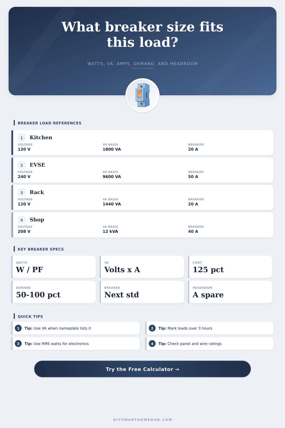
Convert watts or VA into breaker amps, apply the 125% continuous-load rule, account for demand factor, select the next standard breaker, and compare the result against installed breaker headroom.
| Range | Common standard sizes | Calculator use | Planning note |
|---|---|---|---|
| Small branch circuits | 15, 20, 25, 30 A | Rounds up adjusted amps | Use the next size only when conductor and equipment ratings allow it |
| Appliance and feeder circuits | 35, 40, 45, 50, 60 A | Used for midrange loads | Continuous loads can push a circuit into the next breaker size quickly |
| Large residential loads | 70, 80, 90, 100, 110, 125 A | Used for EV, shop, and subfeed examples | Compare breaker rating against panel, disconnect, and feeder limits |
| Service and equipment feeders | 150, 175, 200, 225, 250 A | Upper planning range | Detailed code load calculations may supersede a simple load schedule |
| System | Formula | Typical use | Example result |
|---|---|---|---|
| 120 V single phase | Amps = VA / 120 | Lighting, receptacles, controls, racks | 1,800 VA = 15.0 A |
| 240 V single phase | Amps = VA / 240 | Heaters, EVSE, pumps, split systems | 9,600 VA = 40.0 A |
| 208 V three phase | Amps = VA / (1.732 x 208) | Balanced shop or commercial equipment | 12 kVA = 33.3 A |
| 480 V three phase | Amps = VA / (1.732 x 480) | Larger equipment feeders | 25 kVA = 30.1 A |
| Load type | VA basis | Multiplier | Calculator treatment |
|---|---|---|---|
| Continuous lighting or rack load | Watts / PF or listed VA | 125% | Continuous VA is multiplied by 1.25 before amp calculation |
| Noncontinuous appliance load | Nameplate VA | Demand factor | Noncontinuous VA is multiplied by the entered demand percent |
| Mixed branch circuit | Largest of watts/PF and VA | Split by share | Continuous share gets 125%, remaining VA gets demand factor |
| Planning reserve | Breaker rating | Reserve percent | Target capacity equals breaker amps x (1 - reserve percent) |
| Scenario | Input load | Adjusted load | Breaker cue |
|---|---|---|---|
| Smart home rack | 1,250 W at 0.92 PF, 100% continuous | 1.70 kVA, 14.2 A at 120 V | 20 A breaker keeps about 5.8 A spare |
| EV charging load | 9,600 W at 1.00 PF, 100% continuous | 12.0 kVA, 50.0 A at 240 V | 50 A minimum, larger only if equipment allows |
| Workshop tools | 5,500 W at 0.88 PF, 20% continuous | 5.63 kVA, 23.5 A at 240 V | 30 A standard size before reserve check |
| Three phase shop | 12 kVA, 35% continuous, 75% demand | 10.95 kVA, 30.4 A at 208 V | 35 A standard size, compare to installed breaker |
Use listed VA when a load nameplate gives it. If only watts are available, the calculator divides watts by power factor so low-PF motors, drivers, or power supplies are not understated.
Keep loads expected to run for three hours or longer in the continuous share. The calculator applies the 125% multiplier only to that portion, then adds demanded noncontinuous VA.
When determining the loads that a circuit can take, it is important to ensure that the circuit can handle the amount of electricity that will be used during actual use of the circuit. The number of devices that youre going to connect to the circuit are not necessarily a factor in determining the size of the breaker that is to be used on that circuit. The first step in determining the size of the breaker that are to be used on a circuit is to determine the difference between real power and an apparent power.
Real power, which are measured in watts, is the amount of power that the devices that are connected to the circuit actualy use. Apparent power, which is measured in volt-amps (VA), is the total amount of power that the circuit draws. Many devices, such as motors, electronics, and LED lights, do not have the same amount of real power then apparent power.
How to Size a Circuit Breaker
In these instances, the power factor is used to even out the differences between the two types of power. If the factor is low, more current will travel through the circuit to the devices, which could result in the circuit or breaker overheating. The second step in breaker sizing is to determine the difference between continuous and noncontinuous loads.
A continuous load are a load that is to be continuously operated for three hours or more. Continuous loads require the use of 125% multiplier to ensure that the heat building up from the continuous use of the load does not damage the wires leading to the devices or the breaker. Noncontinuous loads are those that do not continuously operate for three hours or more.
These types of loads do not need to use a 125% multiplier, since they do not build up as much heat before switching off to the devices. Using a 125% multiplier to continuous loads insures that the electrical components dont overheat. The third step in determining the size of the breaker for a circuit is to determine the demand factor.
The demand factor is a percentage that accounts for not all the devices drawing there full power at the same time. For instance, in a workshop, the saw, the dust collector, and the work lights may not all be running at the same time. If there is no demand factor applied to the circuit, the breaker will be sized for the electrical load that could theoretically exist on the circuit.
However, if the demand factor is too low, the breaker will continually trip due to the devices drawing the power that they requires to perform their jobs. To adjust the percentage according to the actual behavior of the electrical equipment
The fourth step involve choosing the size of the standard circuit breaker. The calculated value of the load in amps must be less than the standard value of the circuit breaker.
This is because manufacturers and inspectors of the electrical equipment make the standard circuit breakers. These manufacturers makes circuit breakers in specific amperage values. Furthermore, there must also be some spare capacity on the existing circuit breaker to allow for new electrical equipment to be added in the future.
Additionally, there should be some spare capacity for voltage drops on long wire runs. In selecting the size of the circuit breaker, there is also an 80 percent rule. This indicates that a 20 amp circuit breaker will only carry 16 amps of current.
The same 80 percent rule is applied to circuit breakers as the 125 percent rule for continuous loads. Operating a circuit breaker beyond this limit for many hours will reduce both the life of the circuit breaker and the electrical wires. The voltage of the system will also have an effect on the amperage calculation.
For three-phase power, the load is distributed among three separate circuits. Therefore, three-phase power will require fewer amps than single-phase power for the same value of volt amps. For instance, a value of volt amps at 208 volts for three-phase power will require fewer amps than the same value of volt amps at 120 volts for single-phase power.
The voltage of the circuit will determine the amperage that will flow through the wires. Finally, there are some common mistake when reading the data on the nameplate. For some electrical devices, only the wattage is listed.
For these devices, assuming a power factor of one will lead to incorrect calculations of the number of amps that will flow through the device. Additionally, for some devices the value of volt amps is listed, but the nameplate does not state if that value include the starting surge of the device. In this case, the higher of the two numbers should of been entered into the calculation.
Lastly, the continuous load multiplier and the demand factor should be applied separately. Multiplying these two factors together will lead to an incorrect result.