Battery Cable Sizing Calculator
Size DC battery cables from system voltage, design current, one-way run length, voltage drop target, conductor family, routing derating, and ambient temperature.
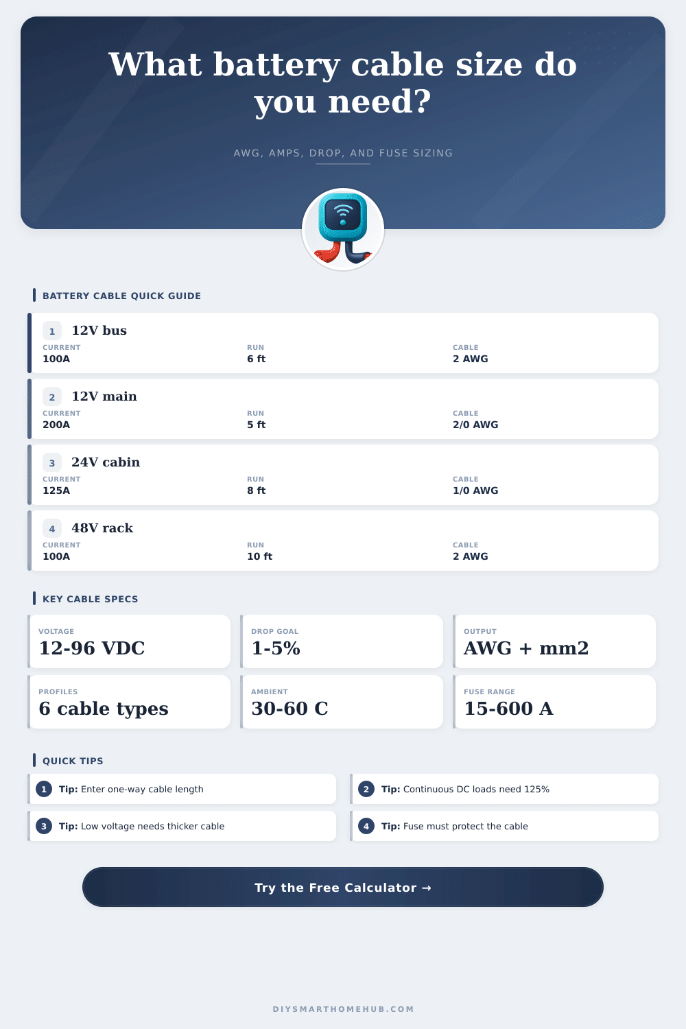
The calculator checks the first cable size that passes derated ampacity, standard DC fuse protection, and the selected round-trip voltage-drop limit.
| Cable size | Area | Copper resistance | Base Cu ampacity | Typical battery use |
|---|---|---|---|---|
| 10 AWG | 5.26 mm² | 0.999 ohm/1000 ft | 30 A | Small DC branch or charger lead |
| 8 AWG | 8.37 mm² | 0.628 ohm/1000 ft | 50 A | Medium DC appliance branch |
| 6 AWG | 13.3 mm² | 0.395 ohm/1000 ft | 65 A | Battery combiner or DC panel feed |
| 4 AWG | 21.1 mm² | 0.249 ohm/1000 ft | 85 A | Short 100 A battery connection |
| 2 AWG | 33.6 mm² | 0.156 ohm/1000 ft | 115 A | 48 V rack or short 12 V main |
| 1/0 AWG | 53.5 mm² | 0.098 ohm/1000 ft | 150 A | Battery main or short inverter link |
| 2/0 AWG | 67.4 mm² | 0.078 ohm/1000 ft | 175 A | Large 12 V battery main |
| 4/0 AWG | 107.2 mm² | 0.049 ohm/1000 ft | 230 A | High-current bank interconnect |
| Battery project | System voltage | Design current | One-way run | Often lands near |
|---|---|---|---|---|
| Ham radio battery lead | 12 VDC | 25 to 35 A | 6 ft / 1.8 m | 8 AWG to 6 AWG |
| 12 V fridge branch | 12 VDC | 10 to 20 A | 15 ft / 4.6 m | 8 AWG to 6 AWG |
| Van house battery main | 12 VDC | 125 to 175 A | 5 ft / 1.5 m | 1/0 AWG to 2/0 AWG |
| 24 V cabin DC bus | 24 VDC | 100 to 150 A | 8 ft / 2.4 m | 1 AWG to 2/0 AWG |
| 48 V server UPS bank | 48 VDC | 70 to 100 A | 10 ft / 3 m | 2 AWG to 1/0 AWG |
| Bow thruster battery feed | 12 or 24 VDC | 300 to 500 A | 12 ft / 3.7 m | 4/0 AWG or larger |
| Condition | Factor | Where it appears | Calculator effect |
|---|---|---|---|
| Battery tray or short raceway | 0.95 | Compact battery box or rack tray | Small ampacity reduction |
| Conduit with nearby conductors | 0.88 | DC panel feed with other circuits | May move up one cable size |
| Bundled 4+ current paths | 0.80 | Parallel banks or stacked harnesses | Strong heat buildup allowance |
| Hot engine or equipment bay | 0.75 | Mobile battery compartments | Larger cable for heat margin |
| 60 C ambient | 0.71 | Very hot enclosed cabinet | Major ampacity reduction |
| Load type | Target drop | Why it matters | Good calculator setting |
|---|---|---|---|
| Radio, router, control electronics | 1 percent | Keeps low-voltage electronics stable | 1 percent sensitive electronics |
| Battery main or inverter input | 2 percent | Limits heating and protects surge voltage | 2 percent battery main |
| General DC lighting branch | 3 percent | Balances cable size and voltage delivery | 3 percent general DC branch |
| Intermittent pumps or tools | 4 percent | Works when run time is short | 4 percent intermittent load |
| Starter or cranking lead | 5 percent | Short surge loads tolerate more sag | 5 percent cranking or short surge |
Flexible copper battery cable
Common for battery-to-busbar, bank interconnect, and short DC feeder work. The calculator treats it as copper with modest flex-cable ampacity headroom.
Tinned marine battery cable
Useful in damp or mobile enclosures. The tinning helps corrosion resistance, while the calculator applies a small resistance allowance.
Fine-strand welding cable
Very flexible and popular for short battery links. Final suitability still depends on jacket rating, terminals, and the cable listing for the environment.
Aluminum battery feeder
Can work for larger stationary feeders with compatible lugs. It usually needs a larger size than copper because resistance is higher.
When installing electrical equipment like an inverter or winch in a vehicle, it is common to experience electrical issues such as flickering lights or voltage low alarm. These issues are typically the result of using electrical cables that are too thin for the electrical loads of the equipment you are trying to power. The thinner the electrical cable, the more resistance the cables creates to the flow of electricity.
Furthermore, thin electrical cables can act as heating element for the vehicle electrical system and cause the system to function inefficiently. DC electricity are different from AC electricity in that it is more sensitive to voltage drop. In an AC system, such as the electrical system in a home, the voltage levels are high so that a small loss of voltage in the wire is not an issue.
Pick the Right Wire Size for Your Vehicle
In a 12 or 24 volt DC system, though, the loss of even one volt result in a significant loss of the power that is being delivered to the device. Small DC cables create resistance in the metal that fights against the flow of the electrical current. This resistance to the flow of electricity act to take voltage away from the device that the electrical system is powering.
Many people focus on the ampacity of the wire to ensure the wire will not melt. However, the wire can be safe from melting but too small for provide the voltage needed by the device. To properly design an electrical system, you have to determine the design current of the system.
The current that you use to determine the size of the cable should not be the current labeled on the device that you are using in the vehicle. Devices can have varying power requirement. For instance, an inverter may require higher amperage when starting up than when it is in operation.
Pumps will draw more power when they are first starting than when they are running. You should always add a safety margin to the loads that you calculate as the current can make the cable warm. Warm copper has a higher resistance than cold copper.
This resistance will affect the performance of your electrical system. The physical path of the electrical cable must be considered when designing the system. For DC current, the path of the current must be complete round trip.
This means that the current has to leave the positive terminal of the battery, pass through the device to be powered, and return to the battery through the negative electrical path. If the length of the wire is six feet, this is twelve feet of wire that will create a voltage drop due to resistance in the metal. The total length of the circuit have to be calculated in order to account for all of the resistance that the wire will create.
The place where the cable is installed is also important to the electrical system. If you install the cable in a tight spot in the vehicle, it will not be able to dissipate the heat that is created by the electrical current. In contrast, the cable will dissipate the heat if it is installed in an open area in the vehicle.
High levels of heat will increase the resistance of the cable. High heat will also affect the insulation on the cable as it may soften and fail. Because heat plays a significant role in the electrical system, derating factor for heat must be used.
These derating factors will require the use of a thicker electrical cable than is recommended in the electrical systems specification. The type of cable that you use will change the function that the cable plays within the electrical system. For example, you can use flexible copper cable for easy routing of the wire in the vehicle.
However, if the electrical system is exposed to salt air or damp environment, the tinned marine cable will be better for withstanding these elements. The tinning on the cable will prevent the copper from oxidizing. By preventing the copper from oxidizing, you are preventing the development of resistance at the electrical terminals.
Other materials, like stiff THHN wire, can be used if the system does not need to bend as much. Lastly, you must use a fuse in your electrical system. The fuse is not for the protection of the device but for the protection of the electrical cable.
If there is a short circuit in the electrical system, the battery will provide a high amount of current through the cable. Without a fuse, this can lead to the cable overheating and potentially igniting a fire in the vehicle. The fuse must be sized appropriately to the derated ampacity of the cable.
If the fuse is too large, the cable will melt before the fuse can protect it. However, if the fuse is too small, it will blow with any power surge in the device. The goal in designing the electrical system is to ensure the voltage remains stable in the vehicle, regardless of the electrical load.
Although thicker electrical cables are more expensive and may be more difficult to bend to the required angle, they will keep the electrical devices stable and allow the batteries to last longer. By properly considering voltage drop, heat in the cable, and properly fusing the electrical system, you will create a reliable electrical system in the vehicle. By using the correct type of cable and fuses, the electrical system will function reliably.