AC to DC Power Calculator
Estimate DC watts, required AC input watts, VA, RMS input current, rectified peak voltage, and smoothing capacitance for common low-voltage smart home loads.
⚙Real-World Presets
🔌Power Inputs
📊Calculated Spec Grid
📐Formula Reference
| Quantity | Formula Used | Notes | Unit |
|---|---|---|---|
| DC output power | Vdc x Idc | Regulated load power after conversion losses | W |
| AC input watts | DC watts / efficiency | Real input power drawn by converter | W |
| AC volt-amps | Input watts / power factor | Apparent power that sizes upstream AC current | VA |
| RMS AC current | VA / Vac RMS | Line or transformer current estimate | A |
| Rectified peak | Vac x 1.414 - diode drop | No-load capacitor peak before regulation | V |
| Capacitance | I / (f x Vripple) | Full-wave uses twice AC frequency | F |
🔧Topology Reference
| Topology | Typical Efficiency | Typical PF | Best Fit |
|---|---|---|---|
| Regulated switching supply | 82% to 92% | 0.55 to 0.95 | Routers, hubs, cameras, controllers |
| Isolated SMPS module | 85% to 94% | 0.90 to 0.99 with PFC | Panel supplies and distributed DC buses |
| Linear regulator after rectifier | 35% to 70% | 0.45 to 0.70 | Low-noise, low-current analog rails |
| Bridge rectifier + capacitor | 70% to 90% | 0.45 to 0.70 | Unregulated DC before a regulator stage |
| Buck converter from DC bus | 88% to 96% | 1.00 after DC bus | Stepping 24V bus rails down to 12V or 5V |
| USB PD adapter stage | 86% to 94% | 0.60 to 0.95 | Single-board computers and USB-powered hubs |
| Lead-acid float charger | 75% to 88% | 0.65 to 0.95 | Backup power and access-control batteries |
| Active rectifier front end | 90% to 97% | 0.95 to 0.99 | Higher-power compact supplies |
🔋Rectifier and Ripple Reference
| Rectifier | Diodes in Path | Typical Drop | Ripple Frequency |
|---|---|---|---|
| Full bridge silicon | 2 | About 1.4V to 2.0V | 2 x AC frequency |
| Full bridge Schottky | 2 | About 0.6V to 1.0V | 2 x AC frequency |
| Center-tap silicon | 1 | About 0.7V to 1.0V | 2 x AC frequency |
| Half-wave silicon | 1 | About 0.7V to 1.0V | 1 x AC frequency |
| Active bridge | MOSFET path | Often under 0.2V | 2 x AC frequency |
| No discrete rectifier | Internal | Use adapter data | Not capacitor-sized here |
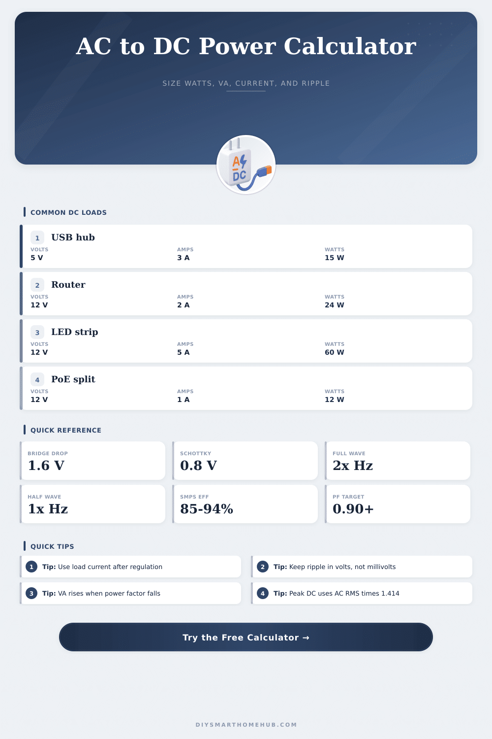
🏠Common Smart Home DC Loads
| Load Type | Common DC Output | Typical Current | Calculated DC Watts |
|---|---|---|---|
| USB hub or small tablet dock | 5V | 2A to 3A | 10W to 15W |
| WiFi router or mesh node | 12V | 1A to 2.5A | 12W to 30W |
| Addressable LED strip controller | 5V, 12V, or 24V | 2A to 10A | 10W to 240W |
| PoE splitter output | 5V or 12V | 1A to 2A | 5W to 24W |
| Security camera | 12V | 0.5A to 1.5A | 6W to 18W |
| Smart relay cabinet | 24V | 0.5A to 2A | 12W to 48W |
| Single-board computer | 5V | 3A to 5A | 15W to 25W |
| Access-control door lock | 12V or 24V | 1A to 3A active | 12W to 72W active |
💡Calculation Tips
When you select a wall adapter or when you open a power supply to run a smart-home device, the numbers on the label dont tell you the full story about the adapter’s power requirements. For example, a 12-volt router may draws two amps when the devices connected to it are all turned on. However, the alternating current component of the router will work more hard than the two numbers on the adapter suggest.
The efficiency of the adapter and the power factor will work against the adapter’s power supply to create a greater demand for alternating current. Understanding the components that impact the adapter will help you make an informed decision about the adapter’s selection, its size, and whether the linear regulator will overheat. The calculator makes it easy to see the relationships between these components.
How to Choose and Size a Power Adapter
By entering the available voltage from the AC wall circuit, the desired DC voltage from the adapter, and the load current, the calculator can tell you how many watts cross the line from the wall to the device, how much apparent power must be supplied to the adapter, and the voltage of the capacitor before the adapter’s regulator regulates it. The calculator can also estimate the bulk capacitor value that ensure that the ripple voltage stays within an acceptable value. These outputs can help you determine whether your available wall circuit can handle these requirements, whether the adapter will overheat, and whether the regulator will remain within its operating limits.
Efficiency is the first of the components that many people often ignore. Because a switching power supply loses around 14 percent of its output due to inefficiency, its DC output will require an input power from the AC wall circuit that is 14 percent higher than the DC power that the load consumes. This extra power is dissipated as heat.
If you are mounting several power supplies in a small area, such heat may cause the electrolytic capacitors in those adapters to not last as long as they are rated to do. The calculator can assist with efficiency because you can enter the efficiency percentage in the calculator’s fields. For linear regulators that come after a rectifier, efficiency will be under 60 percent because the linear regulator will drop the DC voltage across the pass element to obtain the desired DC output voltage.
Thus, a 5-volt DC rail will have different performance depending on whether the 5-volt DC come from a linear power supply or a buck converter. Another important factor is the power factor. With a capacitive input, the current draw pulses of current at the peak of the voltage wave.
This creates a low power factor because the ratio of the real power to the apparent power is low. The ratio can drop to 0.5 or lower. With a low power factor, the current in the wires will be higher than the real watts of the device.
The importance of this component is crucial when sizing a small transformer or an uninterruptible power supply. The calculator can adjust the power factor so that you can see the impact on the current requirements for the wires due to a low power factor. Although most modern switching power supplies has active power factor correction to keep the power factor above 0.95, many older power supplies do not have such active power factor correction.
The type of rectifier will impact the efficiency of the power supply and the peak voltage of the capacitor. A bridge rectifier made of silicon diodes will drop around 1.6 volts across two conducting diodes. Schottky diodes will halve that voltage.
Active bridges made up of MOSFETs can drop the voltage under 0.3 volts. The drop in voltage can be entered into the calculator so that the calculated peak voltage reflects the actual voltage of the capacitor. The peak voltage is important when choosing the capacitor’s voltage rating as well as when feeding a linear regulator so that it does not enter its dropout region.
The relationship between the ripple frequency and the sizing of the bulk capacitor is another important parameter. A full wave rectifier will double the frequency of the input voltage from the wall outlet. If the wall outlet voltage has a frequency of 60 hertz, then the ripple frequency will be 120 hertz.
The formula for calculating the size of the bulk capacitor is the load current divided by the ripple frequency times the allowable ripple voltage. The calculator will make this mathematical calculation for you after you enter the desired ripple voltage in millivolts. The calculator does not take into account the equivalent series resistance of the capacitor and the effect that the load current spikes will have on the capacitor.
Any device with an inductive load will have current spikes when it starts to operate. The load current will spike to a higher value then the steady state current. The capacitor will experience higher rates of charge and discharge than if the current remained at the average value.
Thus, the capacitor that is calculated in the calculator may be smaller than what would be needed for the system. To combat this, many designers of power supplies will either increase the size of the capacitor or use capacitors with a low equivalent series resistance. Some of the devices that are used in smart homes are another important variable in power supply calculation.
A Wi-Fi router with a DC output of 12 volts at 2 amps will draw 24 watts of power. However, the power adapter will be rated at 36 watts to allow for losses due to efficiency and power factor. An addressable LED strip that draws 5 amps at 12 volts may come close to the thermal limits of a small power adapter.
Thus, an addressable LED strip may benefit from having a bulk capacitor of larger size or using a power supply with active power factor correction. A door lock that draws 3 amps of current only while the door is being locked or unlocked may require the power supply to be able to handle higher currents when it is locking or unlocking the door. The values that the calculator provides are only for the steady state operation of the device; you will need to verify that the adapter can handle the inrush current when the device is first turned on.
It is common for people to make a mistake in sizing the power supply components by using the AC current that is provided on the adapter label. The current on that label has already factored in efficiency and power factor to calculate the current that is required from the AC power supply to deliver the DC current to the load. Thus, the label current will not be helpful should you change the load or the power supply topology.
However, if you size the power supply components from the DC side of the power supply, which is what the calculator does, you will have a more accurate sizing of the components of the power supply. Another point to consider is the difference between the peak voltage of the capacitor when there is no load and when the load is running and drawing current. Because of regulation by the transformer and voltage drop from the resistance in the wiring and the voltage drop from the diodes, the voltage will be lower at the capacitor at full load.
The theoretical voltage can be calculated and entered into the calculator; however, the actual measured voltage will be lower by a few volts. Thus, headroom must be left in the sizing of the capacitor and the dropout voltage of the linear regulator. Another important consideration is the effect of temperature and lifetime of the power supply.
If the power supply uses electrolytic capacitors, then the lifetime of those capacitors will halve for every 10 degrees that the temperature is above the rated temperature of the power supply. Thus, a power supply that runs at 60 degrees within a small cabinet will have a reduced lifetime compared to a supply that runs at 40 degrees. For a 10-year lifetime, larger capacitors and some form of forced airflow may be required.
The ripple current can be used to calculate whether reducing the bulk capacitor size will reduce the cost of the power supply and its heat output, or whether the size of the bulk capacitor will have to be maintained to protect the linear regulator from excessive ripple current. Thus, power supply designers want their power supplies to be cool to the touch, to provide a stable voltage to the loads, and to last for long periods of time before the components fail. The calculator can provide a way of exploring these relationships.