Z-Wave Repeater Ratio Calculator
Estimate the right powered-node ratio for a classic Z-Wave mesh by weighing sleepy devices, FLiRS endpoints, floors, wall loss, beaming coverage, and route redundancy headroom.
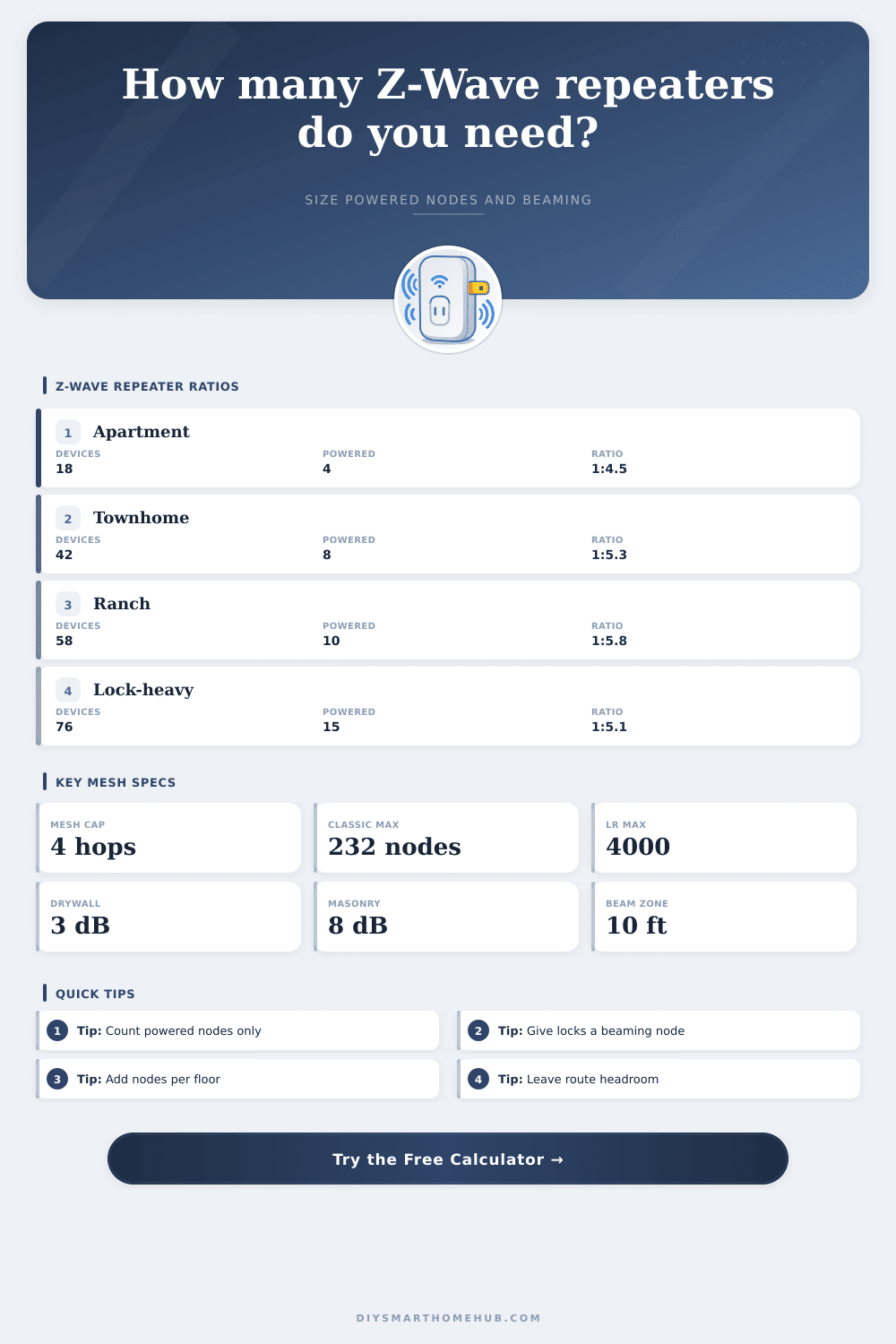
📌Real Z-Wave repeater presets
Loaded preset: Apartment Lock. The model sizes powered repeaters by coverage, endpoint ratio, floor distribution, redundant route headroom, and beaming-node coverage.
⚙Powered-node ratio inputs
Full Z-Wave repeater ratio breakdown
📶Z-Wave and repeater spec comparison grid
📊Reference tables
Powered node ratio bands
| Final ratio | Mesh read | Typical use | Planning response |
|---|---|---|---|
| 1:3 to 1:5 | Dense | Locks, masonry, many floors | Usually strong if beaming nodes are placed near endpoints. |
| 1:5 to 1:7 | Balanced | Most mixed homes | Good starting range with route reserve and floor spread. |
| 1:7 to 1:9 | Lean | Open plans with few FLiRS nodes | Watch the longest span and sleepy-device rejoin behavior. |
| Above 1:9 | Tight | Too many battery endpoints | Add powered routing nodes before adding more sensors. |
Wall and floor factors
| Path profile | Modeled loss | Coverage factor | Ratio effect |
|---|
FLiRS and beaming planning
| Endpoint mix | Beaming target | Powered placement | Reason |
|---|---|---|---|
| One door lock | 1 nearby beam node | Within about 10 ft / 3 m | Improves final-hop wake delivery for lock traffic. |
| Two to four locks | 2 to 3 beam nodes | Near entry zones | Separates front, garage, patio, and basement routes. |
| Thermostats or barriers | One per zone | Same floor when possible | FLiRS endpoints listen briefly and need clean final hops. |
| No FLiRS endpoints | Optional | Use normal powered density | Sleepy sensors wake and report through parent routes. |
Classic mesh vs Long Range
| Z-Wave mode | Topology | Repeater use | Ratio meaning |
|---|---|---|---|
| Classic direct | Hub to node | None | Ratio still matters for the rest of the mesh. |
| Classic routed | Mesh | Powered nodes repeat | This calculator sizes the powered-node density. |
| S2 routed | Mesh | Powered nodes repeat | Use stronger reserve for secure locks and barriers. |
| Z-Wave Long Range | Star | No mesh repeaters | Use direct range planning, not repeater ratio. |
📘Common Z-Wave repeater scenarios
| Scenario | Area | Endpoint mix | Powered node target |
|---|---|---|---|
| Apartment with lock | 600 to 950 sq ft | 12 to 24 sleepy, 1 FLiRS | 3 to 5 powered nodes |
| Two-floor townhome | 1,200 to 1,800 sq ft | 28 to 48 sleepy, 2 FLiRS | 7 to 10 powered nodes |
| Long single-story ranch | 1,800 to 2,600 sq ft | 36 to 65 sleepy, 2 FLiRS | 9 to 13 powered nodes |
| Basement and utility zones | 1,000 to 1,600 sq ft | 20 to 42 sleepy, valves | 6 to 9 powered nodes |
| Lock-heavy security home | 2,400 to 3,800 sq ft | 70+ sleepy, 4+ FLiRS | 14 to 20 powered nodes |
✅Z-Wave ratio tips
A Z-Wave mesh network require a certain balance between battery-powered device and mains-powered devices in order to function correctly. A Z-Wave mesh network that includes only a few Z-Wave devices may function well, but can experience late reports and fail commands from the devices if too many battery-powered devices are added to the network. This is because battery-powered devices is not able to repeat the signals that travel through the network; instead, the mains-powered devices must repeat those signals to the battery-powered devices.
The Z-Wave repeater ratio is the number of battery-powered and FLiRS devices divide by the number of mains-powered devices in the network that can repeat the signals to the battery-powered devices. You can use a calculator to determine the Z-Wave repeater ratio for a network by entering the square footage of the house, the number of floors in the house, the number of mains-powered device that are already in the house, and the wall profiles for the house. The wall profile for the house is important in determining the Z-Wave repeater ratio for a few different reason.
How many mains powered devices do you need for a Z-Wave network
Z-Wave signals has limited coverage, and the walls in the house can act as obstructions to those signals. A mains-powered device may be able to effectively control many battery-powered devices on a floor with drywall on all sides of the device, but the same device may not be able to effectively control battery-powered devices if the walls in the area of those devices include brick fireplaces or foil-backed insulation. The calculator take this into account in the calculation of the target Z-Wave repeater ratio; it adds a “coverage tax” to the calculation that accounts for the need for additional mains-powered devices in the house to overcome the signal loss that occurs with these wall obstructions.
Floors in the house can also impact the Z-Wave signal strength; the signals also weaken when passing through floor joists and subfloors. Additionally, Z-Wave signals have a limit of four hops in distance from the controller in the network. Thus, a mains-powered device that is located on one floor may need to include another mains-powered device in the path that controls the battery-powered devices on a higher floor in the house.
The calculator accounts for the floors in the house so that the mains-powered devices are distribute vertically throughout the floors to prevent dead spots in the control of the battery-powered devices. It is also necessary to distinguish between regular battery sensors and FLiRS devices in the house. Battery-powered sensors wake up on a regular schedule to scan for events in the area of those sensors, but FLiRS devices, such as Z-Wave door locks, only listen for a few seconds for a signal before they go back to sleep.
Thus, the last hop in the path from the controller to a FLiRS device must include a mains-powered device that is able to “beam” the signal to the FLiRS device; it cannot route the signal through another battery-powered device. The number of mains-powered devices that are beaming capable is, therefore, a separate calculation from the total number of mains-powered devices. It is possible that there are enough mains-powered devices to control the battery-powered devices in the house, but there may not be enough beaming capable device to control the FLiRS devices.
The ability of the network to include redundancy in the path that controls battery-powered devices. The calculator allows for the user to choose from a few levels of redundancy, such as basic, balanced, strong, and critical reserve. Higher levels of redundancy require more mains-powered devices than basic redundancy; the higher levels of redundancy account for the possibility of one path being block so that another path exists for the signals to follow.
To implement high redundancy with the network, the mains-powered devices should be located on each floor in the house rather than all of the mains-powered devices being located near the Z-Wave controller. The target Z-Wave repeater ratio can indicate whether the Z-Wave mesh network that is established in the house is healthy or not. If the target ratio is tighter than one mains-powered device for every five or six battery-powered devices in the house, the network may experience issue.
A Z-Wave repeater ratio that is looser than one to nine may work for an open house with few FLiRS devices, but will fail if any of the sensors are placed behind a fireplace or in a basement in the house. Individuals who attempt to calculate the Z-Wave repeater ratio for their house make many mistakes. One mistake is to believe that all devices in the house are the same; battery-powered motion sensors and battery-powered leak detector will not repeat packets of data for other devices in the network, so their addition to the network will still increase the number of battery-powered devices in the network.
Another mistake is to believe that adding a single mains-powered repeater in the center of the house will work to control the battery-powered devices in all of the room of the house at the same time. Each mains-powered device has a limited range for controlling those battery-powered devices; that range decreases if the mains-powered device must send the signal to the battery-powered device through a wall or floor. The calculator is a tool that can be used to plan out the Z-Wave mesh network for the devices in the house prior to purchasing the devices.
If the calculator shows that there are not enough mains-powered devices in the house, those mains-powered devices may be purchased; they may be plug-in modules for mains-powered devices or they may be the replacement of existing mains-powered wall switches with Z-Wave switches. Some battery-powered sensors may be moved to Z-Wave Long Range so that those sensors does not have to use the Z-Wave mesh network. Thus, the Z-Wave repeater ratio calculator acts as a planning tool to determine how many mains-powered devices will be require for the Z-Wave mesh network.
In using this calculator, the goal is to establish a Z-Wave mesh network that can control all of the devices in the house, even if most of those devices is awake at the same time, and even if one of the mains-powered devices in the network should fail.