Yagi Antenna Range Calculator
Estimate clean line-of-sight range, midpoint Fresnel clearance, link budget headroom, and aiming tolerance for Yagi-based Wi-Fi, LoRa, LTE, and smart property backhaul links.
| Yagi Profile | Typical Gain | Half-Power Beam | Planning Use |
|---|---|---|---|
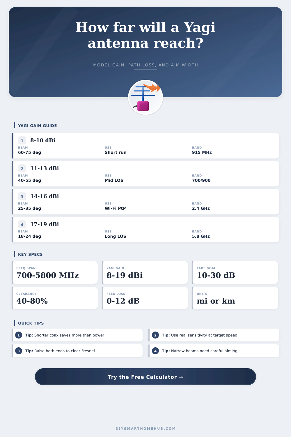
| Compact 915 MHz Yagi | 8 to 9 dBi | 60 to 75 deg | Gate sensors, utility telemetry, and short rural links |
| Long 915 MHz Yagi | 10 to 12 dBi | 40 to 50 deg | Longer LoRa or sub-GHz links where mounting room exists |
| 2.4 GHz Wi-Fi Yagi | 14 to 17 dBi | 22 to 32 deg | Garage, barn, or greenhouse point-to-point backhaul |
| 5.8 GHz Microwave Yagi | 16 to 19 dBi | 18 to 26 deg | Clear LOS camera poles and short high-band bridges |
| Band | Fresnel Size | Clutter Tolerance | Directional Note |
|---|---|---|---|
| 700 MHz | Largest zone | Best of group | Big physical Yagis but strong rural penetration for LTE paths |
| 868 to 915 MHz | Wide zone | High | Excellent for telemetry and LoRa where throughput is modest |
| 2.4 GHz | Medium zone | Moderate | Good compromise between Yagi size, gain, and aiming tolerance |
| 5 to 5.8 GHz | Smallest zone | Lowest | Narrow beams and low clutter tolerance demand a very clean path |
| Cable | 900 MHz Loss / 100 ft | 2.4 GHz Loss / 100 ft | Planning Note |
|---|---|---|---|
| RG-58 | 11 to 13 dB | 23 to 26 dB | Usable only for very short jumpers before Yagi gain is wasted |
| LMR-240 | 6 to 7 dB | 13 to 15 dB | Acceptable for modest runs when mast-mounted radios are not possible |
| LMR-400 | 3 to 4 dB | 6 to 7 dB | Common upgrade when the antenna is far from the radio body |
| Direct-mount radio | Near zero | Near zero | Best way to keep directional gain from being erased by coax |
| Scenario | Band | Typical Yagi Pair | Planning Focus |
|---|---|---|---|
| Detached garage bridge | 2.4 GHz | 14 dBi + 14 dBi | Keep both ends above fence lines and metal roofs |
| Driveway gate telemetry | 915 MHz | 8.5 dBi + 8.5 dBi | Reserve extra dB for trees, rain, and low mast heights |
| Rural LTE router | 700 MHz | 11 dBi + tower sector | Profile must match the carrier band and polarization |
| Camera pole backhaul | 5.8 GHz | 16 dBi + 16 dBi | Short coax and precise alignment matter more than raw power |
A 2.4 GHz Yagi cannot be trusted at 900 MHz or 5.8 GHz just because the connector fits. If the profile frequency and operating band diverge too much, expect the real pattern and gain to collapse.
Raise both ends, shorten coax, and fix polarization before pushing more conducted power. Those changes usually improve fade margin and actual reliability faster than trying to overpower a blocked path.
Directional antenna, like Yagi antennas, are used to increase the distance to which a radio signal can travel by focusing the radio energy into a directional beam. Many peoples use directional antennas because they allow radio signals to travel further than an omnidirectional antenna could allow. Omnidirectional antenna radiate signals in many different directions at once, while a Yagi antenna direct radio signals into a single beam.
Because the Yagi antenna directs the radio signals into that narrow beam, the Yagi antenna can provide higher gain to those signal; the higher the gain of a radio signal, the more further that it can travel. A Yagi antenna is only effective within certain frequencies of radio signals and when the antenna are correctly aligned. If a Yagi antenna is not aligned with the destination of the radio signal, the signal will not reach that destination.
How to Use and Install a Yagi Antenna
For instance, a Yagi antenna with high gain will have a very narrow beam of radio signals; if the antenna is even slight misaligned, the signal will not reach it’s destination. Furthermore, the radio signal must contain the same frequency as the Yagi antenna was manufactured for optimal performance. A Yagi antenna designed to work with radio signals of 900 MHz will not perform as well with 5 GHz signals because the wavelengths of these two frequency are different.
Radio signals of low frequencies, such as 915 MHz, can penetrate foliage and other obstacles more effective than high frequencies, such as 5.8 GHz. However, low-frequency Yagi antennas are larger in size than high-frequency Yagi antennas. Thus, a person using a low-frequency Yagi antenna will need to use a stronger mount to hold the antenna.
Additionally, the area around the direct path of a radio signal is referred to as the Fresnel zone; if obstacles to the signal pass through this zone, the signal will weaken. Thus, a person must make sure the two Yagi antennas is mounted high enough to keep the Fresnel zone clear of obstacles. Another factor that can reduce the strength of a radio signal is known as feedline loss.
Feedline loss occur when the coaxial cable (coax) that connects the radio transmitter to the Yagi antenna absorbs some of the radio signal before it can reach the antenna. For instance, if a person uses a light gauge coaxial cable, such as RG-58 for long distance, the signal will be weakened. In order to avoid signal loss, a person can use a more better quality coaxial cable, such as LMR-400; however, the second alternative is to simply mount the radio antenna directly to the mast; shortening the coaxial cable will also reduce the amount of signal lost to feedline loss.
Another factor to consider before installing Yagi antennas is the fade margin. The fade margin are the difference in signal strength between the signal that the radio antennas will emit and the signal that may be absorbed by the environment. For instance, leaves may grow on trees during the spring months, blocking the signals.
Similarly, rain may fall during these months and weaken the signals between the Yagi antennas. Thus, if the fade margin is set to 20 dB, for instance, the signal will remain connected even if the environment change. However, if the margin is much smaller, such as 10 dB, the signal may become interrupted if the environment changes.
Finally, the person installing the Yagi antennas must consider the terrain. The Earth is spherical in shape, and thus, an installation of the Yagi antennas will have a limited range due to the curvature of the planet. Thus, the Yagi antennas should be mounted as high as possible on a pole to increase the distance to which the signal travel.
Additionally, if the terrain is not even, a person may need to mount one Yagi antenna higher than the other so that the signals remains even with one another. Furthermore, if these factor are balanced with each other, the Yagi antenna will emit radio signals of strong enough strength to travel the necessary distance to the other Yagi antenna.