Wind Turbine Spacing Calculator
Plan downwind rotor spacing, crosswind gaps, boundary buffers, row count, and land envelope for micro, cabin, home, and small property wind turbine arrays.
Wind Turbine Spacing Results
| Layout condition | Downwind spacing | Crosswind spacing | Calculator use |
|---|---|---|---|
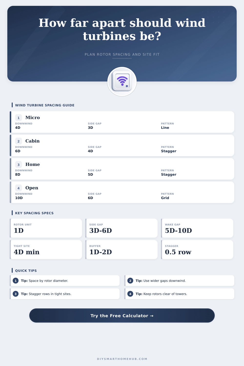
| Micro turbines or training field | 4D to 5D | 2.5D to 3.5D | Compact layouts where output loss is acceptable |
| Cabin or shed battery support | 5D to 7D | 3D to 4D | Balanced small-property planning |
| Home-scale small wind | 7D to 9D | 4D to 5D | Better wake recovery for real charging output |
| Open field multi-row array | 8D to 10D | 5D to 6D | Preferred when land is available |
| Turbulent roof or obstacle zone | 10D or more | 5D or more | Feasibility screen only, turbulence can dominate |
| Exposure profile | Wake factor | What changes | Planning note |
|---|---|---|---|
| Open field or shoreline | 1.00x | Uses entered spacing | Smoother wind lets rotor-diameter rules work best |
| Suburban trees and buildings | 1.12x | Adds 12% spacing | Useful when nearby obstacles create slower wake recovery |
| Wooded or uneven terrain | 1.20x | Adds 20% spacing | Clearance above obstacles matters as much as spacing |
| Ridge or channelled wind | 1.08x | Adds 8% spacing | Long narrow sites often favor one row along the ridge |
| Roof or turbulent structure | 1.35x | Adds 35% spacing | Average speed may not predict vibration or wake quality |
| Project scenario | Typical rotor | Practical pattern | Spacing target |
|---|---|---|---|
| Remote sensor or gate charger | 3 to 5 ft / 0.9 to 1.5 m | Single line or separated masts | 15 to 40 ft between turbines |
| Shed battery wind pair | 5 to 8 ft / 1.5 to 2.4 m | One row across prevailing wind | 25 to 65 ft side spacing |
| Cabin hybrid charging | 8 to 13 ft / 2.4 to 4.0 m | Line or shallow stagger | 50 to 110 ft wake spacing |
| Home-scale tower cluster | 13 to 20 ft / 4.0 to 6.1 m | Staggered two-row array | 90 to 180 ft downwind |
| Farm or coastal field | 20 to 30 ft / 6.1 to 9.1 m | Wide staggered grid | 160 to 300 ft downwind |
| Fit result | Meaning | Layout response | Calculator field to adjust |
|---|---|---|---|
| Comfortable fit | Site exceeds required width and length | Keep chosen spacing and validate setbacks | None unless energy target changes |
| Width limited | Too many turbines side by side | Add rows or use a ridge line layout | Layout pattern or crosswind D |
| Length limited | Rows do not have enough wake recovery | Use fewer rows or accept fewer turbines | Downwind D or turbine count |
| Tight feasibility | Spacing is below normal wake allowance | Treat output as uncertain and monitor vibration | Exposure or boundary buffer |
| Single-row best | Land is long or narrow | Place turbines across the prevailing wind | Layout pattern and site width |
Wind turbine spacing will determine if the wind turbine array produces power or perform poorly. If you place a wind turbine too close to another wind turbine, the second wind turbine will sit in slow and dirty air create by the first. The slow moving air will contain less energy, meaning the second wind turbine will produce less power then it could otherwise.
The spacing between wind turbines is not a number; it must change based on the size of the rotors of the wind turbines, the wind direction, and the available lands for the wind farm. Each of these factors must be weigh in developing a sound plan for the spacing of the arrays wind turbines. One of the first factors to consider in setting wind turbine spacing is the rotor diameter of the wind turbines.
How to Space Wind Turbines
Not only will the rotor diameter impact the scale at which the spacing between the wind turbines will be established, the wake create by each of these rotors will dictate the spacing between each of these turbines. Multiples of the rotor diameter will be used to calculate the distance between each of the wind turbines. Using a smaller number of the rotor diameter to calculate spacing will save land and hardware for the wind farm.
Yet, there will be less margin for error in the wind direction. Using a larger rotor diameter will protect the power output of the wind turbines. However, this may place the wind turbine array beyond the boundaries of the property.
Another important factor to consider is the direction of the prevailing wind in the area. The wake create by the rotating turbines will move in the same direction as the wind. Therefore, the gap between each of the wind turbines is the most important if that gap is measured along the axis of the wind.
Turbine spacing to the sides of the turbine array can be much closer together than the distance between the turbines in the downwind direction. Some utilize a grid layout for their wind farm layout. Yet most opt for a staggered layout of the turbines in each array.
By staggering the placement of each of the arrays in each row, the wind turbines can be placed in the area where the air is the cleanest and contain the most energy for the turbines to extract. The third factor to consider is the site exposure for the wind farm. If the site is exposed to an open shoreline, the wake create by each wind turbine will dissipate quick.
Yet if the location is a wooded hillside or another area with many buildings, the wake will travel longer distances and impact the power output of the turbines located in those areas. An adjustment factor can be made to the general rule for wind turbine spacing to account for these local obstacles. A ridge in the area may allow turbines to be placed closer together because the ridge channels the wind.
These factors can be accounted for in a calculator that will calculate the spacing between each turbine. Additional considerations include allowing space for maintenance vehicles, allowing space for the guy wires for the towers, and allowing space for legal setback rules from the boundaries of the property. These boundaries will reduce the amount of land available for the wind farm.
The layout of the wind farm that appears to suit the dimension of the property may not allow for the boundary buffers. These buffers will protect the turbines from each other should the wind change direction. Many people make mistake when planning the placement of the wind turbines.
A common mistake is using a multiplier for the rotor diameter from a textbook and finding that the placement of the turbines is too large for the boundaries of the property. Another common mistake is placing wind turbines too close together along the side-to-side dimension of the land without considering that the turbine require room for its rotor and yaw mechanisms. A sound plan requires that the person designing the wind farm layout runs the calculations for the layout twice.
They should calculate the placement of the turbines according to the layout they prefer. Yet they should also calculate the placement of the turbines according to the capability of the land. Other factors that can impact the placement of the wind turbines include adherence to the noise rules of the area, the routing of the power generated by the wind turbines, and the height of the towers that will support each wind turbine.
Using a taller tower will allow the turbines to access areas with more energy in the wind. Yet the footprint of the wind farm will increase along with the guy wires require to support the taller turbines. If the wind turbines are to be spaced far apart from each other, the cost of the underground power cables will increase the cost of the wind farm.
The placement of the turbines can have a direct impact on the total budget for the wind farm. Finally, the placement of the wind turbines must account for possible shift in the direction of the wind. Should the shift in the direction of the the wind place many of the turbines in the wake of other turbines, the wind farm will not produce as much energy as it could.
Providing extra gap between the turbines in the crosswind direction or utilizing a staggered area of turbines will provide insurance against wind shifts. Calculators can be used to determine the effect of shifts in the direction of the wind. Yet human observation of the site will reveal shifts in the direction of the wind that occur in different season of the year.