🌬 Wind Turbine Cable Size Calculator
Estimate conductor size for wind turbine tower drops, rectifier leads, battery charge-controller runs, and inverter feeds using voltage drop and ampacity checks.
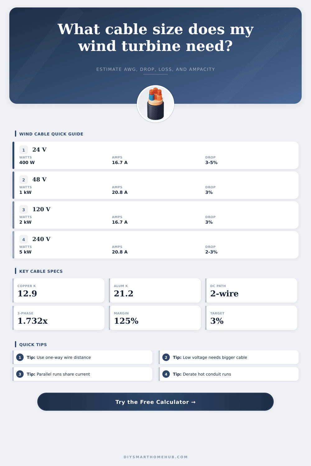
Enter one-way wire distance, not round-trip length. The calculator checks voltage drop first, then verifies ampacity after safety margin, temperature factor, and parallel conductor sharing.
Calculated cable recommendation appears here.
Calculation Breakdown
| Size | Circular mils | Copper amps | Aluminum amps | Best wind use |
|---|---|---|---|---|
| 14 AWG | 4,110 | 20 A | 15 A | Small sensors, short brake leads |
| 12 AWG | 6,530 | 25 A | 20 A | Small 120 V turbine circuits |
| 10 AWG | 10,380 | 35 A | 30 A | Short 24 V or 48 V charging runs |
| 8 AWG | 16,510 | 50 A | 40 A | Common 48 V battery turbine run |
| 6 AWG | 26,240 | 65 A | 50 A | Long low-voltage tower-to-battery leads |
| 4 AWG | 41,740 | 85 A | 65 A | High-current 24 V or 48 V runs |
| 2 AWG | 66,360 | 115 A | 90 A | Long battery-side feeder |
| 1/0 AWG | 105,600 | 150 A | 120 A | Large battery inverter segment |
| 4/0 AWG | 211,600 | 230 A | 180 A | Very high current, very low voltage |
| Segment | Typical voltage | Target drop | Why it matters | Calculator input |
|---|---|---|---|---|
| Turbine to rectifier | 3-phase AC | 2% to 5% | Keeps power capture stable before conversion | Circuit: AC three-phase |
| Rectifier to controller | 24 V to 120 V DC | 2% to 3% | Low voltage amplifies current and loss | Circuit: DC two-wire |
| Controller to battery | 12 V to 48 V DC | 1% to 3% | Battery charging is sensitive to drop | Use actual charge amps |
| Battery to inverter | 12 V to 96 V DC | 1% to 2% | Inverter surge current can be high | Add inverter distance |
| Grid-tie AC output | 120 V to 240 V AC | 2% to 3% | Protects voltage at the interconnect | Circuit: AC single-phase |
| Project | Output | Run length | Likely cable range | Primary limit |
|---|---|---|---|---|
| Shed trickle turbine | 120 W at 12 V | 40 ft / 12 m | 10 AWG to 8 AWG | Voltage drop |
| Cabin hybrid charger | 600 W at 48 V | 120 ft / 37 m | 8 AWG to 4 AWG | Voltage drop |
| Barn battery system | 1.5 kW at 48 V | 180 ft / 55 m | 4 AWG to 1 AWG | Drop and ampacity |
| Shop AC turbine | 3 kW at 240 V | 220 ft / 67 m | 12 AWG to 8 AWG | Drop target |
| Three-phase tower | 5 kW at 240 V | 300 ft / 91 m | 8 AWG to 4 AWG | Long run loss |
| Item | Value used | Applies to | Effect | Result impact |
|---|---|---|---|---|
| Copper K | 12.9 | Voltage drop | Lower resistance | Smaller required circular mils |
| Aluminum K | 21.2 | Voltage drop | Higher resistance | Larger conductor required |
| DC factor | 2.0 | Two-wire loop | Counts out and back path | Higher drop than one conductor |
| Three-phase factor | 1.732 | Balanced AC | Line-to-line drop formula | Often smaller than DC equivalent |
| Safety margin | 125% | Ampacity | Continuous wind output buffer | Raises ampacity requirement |
Ampacity values are practical planning references. Local electrical code, insulation temperature, terminals, conduit fill, grounding, disconnects, and overcurrent protection still need project-specific verification.
Wind turbines can produce different current than nameplate watts divided by nominal voltage, especially around rectifiers, controllers, dump loads, and battery charging profiles.
Long low-voltage wind cables often need large conductors for voltage drop even when ampacity appears comfortable. Short inverter cables often flip the problem.
When a wind turbine is installed on a towers or a pole, a cable is required to carry the electrical power from the wind turbine to the controller or the battery banks. The cable must be able to carry the electrical current from the turbine without overheating the cable and with a low drop in voltage so that the turbine can effectively providing energy to the battery bank. If the cable is not sized appropriately for the electrical output of the wind turbine, the power will be lost in the cable, reducing the amount of power that is available for the wind turbine to charge its battery.
Additionally, incorrectly size cable will become hot with increased wind speeds. To size the cable for a wind system, one must determine the amount of current that will flow through the system and the distance that the electricity must travel. Additionally, one must also determine the amount of voltage loss that can exist before the wind turbine performance decline.
How to Size Cable for a Wind Turbine
As will be discussed later, low voltage wind turbines are more difficult to wire than high voltage wind turbines. This is because low voltage wind turbines have higher amperage outputs for the same amount of wattage produced by the turbine. Therefore, the conductors for the low voltage wind turbines must be larger to allow for the same amount of power to be delivered to the battery bank without losing too much of that energy.
Higher voltage machines will have reduced current requirements, but still require conductors that can handle the high output of the turbine as well as potential surges in that current caused by the gusty and windy environments in which many of these turbines are located. The calculator contained within this article allow an individual to calculate the mathematical components of the sizing requirements for the wire run from the turbine to the battery bank. The calculator first determines the voltage drop that will occur along the cable run, as the voltage drop is often the determining factor for the appropriate size of the cable run.
After calculating the voltage drop, the calculator also determines whether or not the chosen conductor is able to carry the required amount of current from the wind turbine with an appropriate safety margin for the conductor. Changing the type of circuit from DC to three-phase will alter the factor that is used to calculate the voltage drop, which may lead to a change in the size of the cable run. Additionally, the calculator also allows for the testing of the amount of power that can be delivered if multiple runs of the same cables are used in series (parallel runs).
Using multiple cables of lesser gauge sizes may make more sense than using a single conductor for the cable run. Another important factor that must be considered in the sizing of the cable is the distance between the turbine and the battery bank. Such a distance can have a significant impact on the amount of power that is lost as the power travels to the battery bank; the extra distance that exists between the inverter and the controller must also be considered in the calculations.
If the batteries are located in one building and the inverter is located elsewhere, the distance between these two components must be accounted for in the calculation of the cable size. Another important factor is the environment in which the cable is to be installed. If the cable is to be installed in a hot attic or hot conduit, for instance, the ability of the cable to carry current is reduced due to the high surrounding temperatures.
By adjusting for this in the calculations using the derating adjustment, the cable will not come too close to it’s temperature limit. Another factor that impacts the sizing of the conductor is the material from which the conductor is to be manufactured. Copper has a lower resistance than aluminum, which will lead to a reduction of the voltage drop along the cable run.
The cost of aluminum is less than copper for the same amount of ampacity. However, because aluminum has a higher resistance than copper, a larger conductor of aluminum will be required to provide the same amount of power to the battery bank as a conductor of copper. These different electrical properties of the two materials are accounted for in the calculator; the calculator includes the material constant in its calculation of the circular mils of the cable run.
Most installers will choose copper for the run from the wind turbine to the battery bank; however, the cost of aluminum may be more important than the increased size of conductor that is required for the aluminum. The reference tables that are provided on the page are not a replacement for the calculations performed with the calculator. The reference tables include the size of the conductors of various ampacities and circular mils sizes.
Additionally, the tables also include the voltage drops that are targeted within various components of the wind system. For instance, the voltage drops that are targeted for the run from the battery bank to the inverter will be different than those targeted for the run from the turbine to the controller. The voltage drop for the batteries needs to be very low because small voltage differences will impact the amount of power that is delivered to the batteries.
Additionally, the cables from the inverter will have high surge currents, so they will need to be sized accordingly. Some of the most common mistakes for those sizing the cables for wind systems is to only consider the ampacity of the cable; sizing the conductor for only ampacity may result in the voltage drop to the controller being too low for the turbine’s performance. Other common mistakes is to size the cable according to the voltage drop yet to forget to include the 125% factor for the continuous use of the conductor or the temperature adjustment to the ampacity of the conductor.
If either of these factors is omitted, the cable may become too hot for the environment in which it is installed. Using parallel conductors can help to avoid both of these issues, but the ampacity of the individual conductors must be determined with the calculator. In addition to those calculations and recommendations provided by the calculator, there are some additional considerations for real world installations of these types of systems.
For instance, electrical codes will require specific types of conductors or insulation for the cables. Additionally, the terminals located on the inverters and controllers may only allow for specific sizes of electrical conductors, which may require a size of conductor that is larger than that calculated with the calculator. The location of the wind turbine may also have an impact on the sizing of the conductor; wind gusts may create spikes in the current that travel through the cable run.
These spikes in the current will require the establishment of a safety margin for the current in the conductor. The goal for the sizing of the conductor is to not have an infinite loss of power through the cable to the battery bank. However, the losses in the cable must be low enough so that the turbine can effectively charge the batteries while remaining within the temperature limits of the conductor.
These targets can be seen in the breakdown section of the calculator; the breakdown section of the calculator displays the amount of power from the turbine that is lost to the cables, as well as the margin for the ampacity of the conductor. These two values will help an installer to understand whether the sizing of the conductor is determined by the voltage drop, the current capacity of the conductor, or both. Choosing the right cable for a wind turbine will require someone to understand each of these factors that may impact the sizing of that conductor.
For instance, by understanding the distance between the turbine and the battery bank, the temperature that the cable will reach, and how many extra amps are desired in the cable, an individual can make an informed decision about the size and type of conductor that will best function within the system.