WiFi Yagi Antenna Calculator
Calculate element lengths, spacing, boom length, estimated gain, beamwidth, and feedline-adjusted gain for 2.4, 5, and 6 GHz directional WiFi antennas.
🎯Real WiFi Yagi Presets
📡Antenna Inputs
Calculation Breakdown
⚙Calculated Spec Grid
📋Element Cut and Position Table
| Element | Length | Position From Reflector | Spacing From Prior | Purpose |
|---|---|---|---|---|
| Reflector | 61.4 mm | 0 mm | — | Rear rejection |
📶WiFi Band Reference
| WiFi channel | Center frequency | Free-space wavelength | Typical driven length | Useful for |
|---|---|---|---|---|
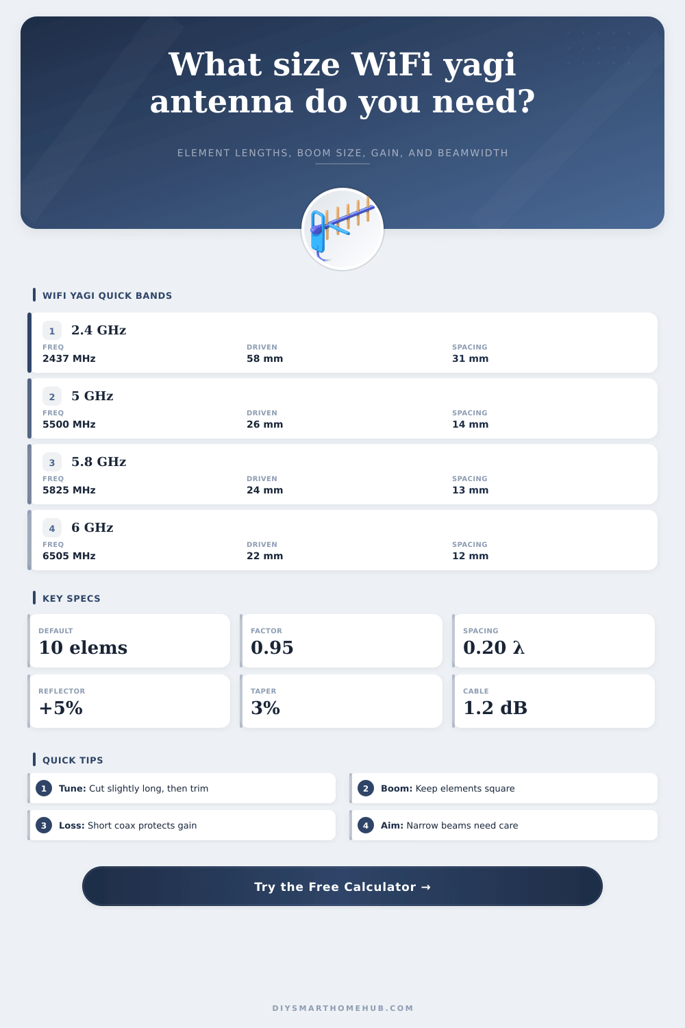
| 2.4 GHz Ch 1 | 2412 MHz | 124.3 mm / 4.89 in | 59.0 mm / 2.32 in | Lower 2.4 GHz links |
| 2.4 GHz Ch 6 | 2437 MHz | 123.0 mm / 4.84 in | 58.4 mm / 2.30 in | Common 2.4 GHz center |
| 2.4 GHz Ch 11 | 2462 MHz | 121.8 mm / 4.79 in | 57.9 mm / 2.28 in | Upper 2.4 GHz links |
| 5 GHz Ch 36 | 5180 MHz | 57.9 mm / 2.28 in | 27.5 mm / 1.08 in | Indoor directional tests |
| 5 GHz Ch 149 | 5745 MHz | 52.2 mm / 2.06 in | 24.8 mm / 0.98 in | Outdoor point links |
| 6 GHz Ch 117 | 6505 MHz | 46.1 mm / 1.82 in | 21.9 mm / 0.86 in | Compact 6E builds |
🔧Element Factor and Material Table
| Build style | Starting factor | Diameter guidance | Calculator use | Design note |
|---|---|---|---|---|
| Thin copper wire | 0.960 | 0.8–1.6 mm | Longer cuts | Easy to trim but bends easily |
| Brass or copper rod | 0.950 | 2–4 mm | Default choice | Good balance for WiFi yagis |
| Aluminum tube | 0.940 | 4–8 mm | Shorter cuts | Broader bandwidth, stronger boom |
| Printed copper trace | 0.940 | Trace geometry | PCB starting point | Needs board-specific tuning |
📊Common WiFi Yagi Size Table
| Scenario | Frequency | Elements | Boom range | Gain range |
|---|---|---|---|---|
| Apartment room aim | 2.437 GHz | 6–7 | 135–165 mm | 9–10 dBi |
| Garage bridge | 2.437 GHz | 9–10 | 200–235 mm | 11–12 dBi |
| Shed link | 5.745 GHz | 10–12 | 95–125 mm | 12–14 dBi |
| Long narrow path | 5.825 GHz | 13–15 | 135–160 mm | 14–15 dBi |
| Compact 6E lab link | 6.505 GHz | 8–10 | 70–92 mm | 11–12 dBi |
🧭Design Tips
A yagi antenna is a directional antenna that can be used with a WiFi router to focus the outgoing WiFi signals into a narrow beam. A yagi antenna is useful for people who needs to send a signal from their router further than a standard router can send a signal. Many people use a yagi antenna calculator to determine the dimensions that their antenna should has.
Each of these calculators ask for the frequency of the signal that is to be transmitted, the number of elements that will be present on the antenna, and the materials from which the antenna will be made. After these variables are entered, the calculator will perform the calculations that the antenna designer would otherwise have to perform and return the dimensions for which the antenna elements should be made. Thus, this calculator allows the designer to avoid focusing on the mathematics involved in designing such an antenna.
How to Use a Yagi Antenna Calculator
Most antennas will emit energy in various direction. A yagi antenna, however, is constructed in such a way that only a narrow beam of energy is emitted. More specifically, a yagi antenna include elements that work together to create this narrow beam of energy.
A yagi antenna includes a reflector that is placed behind the driven element of the antenna, and the yagi antenna also includes several directors that are attached to the driven element; these elements are all of a length that creates a phase relationship that reinforces the signal in the forward direction of the antenna and causes the signal to cancel itself out in the backward direction of the antenna. Additionally, the yagi antenna calculator also incorporates a factor that accounts for the thickness of the material from which the antenna is made. For instance, if rods of thick material are use to make the antenna elements, the element factor that is used in the calculator will be around 0.95; for tubing, the element factor will be around 0.94.
Another factor to consider in the construction of a yagi antenna is the number of elements that are to be included in the antenna. The more directors that are added to the antenna, the higher the gain that the antenna will have in the forward direction. However, as the number of elements increase, the beamwidth of the antenna will narrow.
For example, a seven-element yagi antenna may provide a gain of ten decibels at 2.4 GHz, and the beamwidth of the antenna will allow for small error in aiming the antenna at the receiving device. If, however, the antenna is to have twelve or fifteen elements, it will provide higher gain; however, the aiming of such an antenna will have to be more precise. This necessity for precision aiming is even more significant for antennas that are to emit signals at 5 GHz or 6 GHz.
Thus, the yagi antenna calculator can provide an estimate of the beamwidth of the antenna; this beamwidth can help determine whether the mounting location for the antenna allow for the precision in aiming that is required by the number of elements that are to be present on the antenna. In addition to the number of elements that are to be made up the yagi antenna, another factor that must be considered in the construction of the antenna is the spacing between each of those elements. The spacing between elements should be set between a range of 0.18 to 0.22 wavelengths of the emitted signal; if the spacing between elements is set too small, the gain of the antenna will drop; if the spacing is too large, the boom length of the antenna will be too long for it to be mounted onto a mast.
Thus, the spacing between elements can be adjusted in the calculator, and altering the distance between the elements will alter the calculated length of the boom of the antenna and the gain that the antenna can achieve. In addition to the variables that the antenna calculator can determine, additional considerations regarding the materials from which the antenna will be made and the locations at which it will be mounted can impact the performance of the antenna. For instance, metal booms touching the elements of the antenna will require those elements to be insulated from the metal; nearby objects may lower the resonant frequency at which the antenna performs; each of these elements will require the antenna to be cut to the correct lengths before mounting.
Thus, while the antenna calculator can prepare the antenna to the specifications that are required for best performance, the actual antenna will have to be built once it is mounted to the mast. Another factor to consider when employing a yagi antenna at 5 GHz is the potential loss of signal that may occur in the feedline between the router and the antenna. Signal loss in an RG-58 cable at 5 GHz will be higher then that which travels at 2.4 GHz; thus, the signal strength will be reduced due to the properties of the cable.
The link budget for the antenna and WiFi router system can be increased by moving the router closer to the antenna, or by employing a cable with less signal loss. The yagi antenna calculator can ask for the length of the feedline between the router and antenna, as well as the signal loss per meter of that length; this signal loss will be incorporated into the gain that is calculated by the antenna calculator. A fifth factor to consider in the use of a yagi antenna is the aiming of the antenna.
A fifteen-element antenna that emits signals at 5.8 GHz has a beamwidth of less than thirty degrees; thus, if the antenna that is mounted to the mast begins to move, even slightly, the signal strength will drop. A signal-strength meter can be used to find the peak signal strength that is emitted by the antenna; the antenna can be slowly moved in small increments until the strongest signal is located. The calculator cannot indicate the location of the strongest signal; however, it can determine the beamwidth of the antenna, which will allow the individual to prepare their mounting hardware for the antenna.
The reference tables that are provided with the calculator display the lengths of each of the antenna elements for different WiFi channels. These tables provide context for the frequency at which the signal will be sent; however, the same rules apply for all of the channels and frequencies. Antennas for channels such as 149 will have elements of shorter lengths than antennas for channels such as six.
However, the physics of the antenna are the same regardless of the channel for which the antenna is built. Thus, the element factor, the reflector boost, and the taper percentages are all factors that will be found to be useful when building the antenna; the physics of the yagi antenna are linear with respect to the wavelength of the emitted signal. Additionally, the factors of tolerance in building the antenna becomes more important at higher frequencies; small errors in length of the elements will have a larger percentage of impact on the antenna at 6 GHz than at 2.4 GHz.
The calculator can be used multiple times to determine the specifications for the antenna. For example, the calculator can be used once with the entered values of the parameters that are likely to exist for the antenna; a second use of the calculator can ask for more elements in the antenna, as well as ask for the realistic loss in the feedline that connects the antenna and the router. Through performing each of these calculations, a designer can determine whether the extra effort and cost to build an antenna with more elements will provide enough additional gain to the signal to warrant such an effort.
In most cases, the answer to this question will be no; a simple yagi antenna will provide enough signal strength to the target devices, and will be easier to mount to a mast than an elaborate antenna structure. The use of the yagi antenna calculator removes the manual calculations that must be performed for each of the parameters of the antenna; however, the designer must still consider each of the other variables in building the antenna. For instance, the designer must determine where the antenna will be placed, how long the feedline will be, and how precisely it will be aimed.
These variables will determine whether the antenna will successfully create a reliable data connection, or whether the antenna will fail to function altogether.