Underfloor Heating Flow Rate Calculator
Estimate radiant floor loop flow from BTU or kW load, delta-T, glycol mix, pipe size, loop length, spacing, manifold ports, and balancing targets.
🎛1. Load a manifold or zone preset
Each preset fills a real-world radiant floor scenario with heat load, loop count, pipe, spacing, loop length, delta-T, glycol, and manifold meter range.
📏2. Enter the radiant floor details
Recommended radiant floor flow
Use the calculator to size loop flow, manifold total, and a pump head hint for the selected zone.
🧮3. Pipe, pump, and manifold spec grid
Most residential manifolds read best in the middle of this per-loop range.
Common practical maximum loop length before balancing gets fussy.
Typical hydronic velocity comfort band for small radiant pipe.
Radiant floor circuits often land here depending on slab, plates, and controls.
📊4. Reference tables
| Pipe or tubing | Approx inside diameter | Common loop length | Useful flow band | Calculator role |
|---|---|---|---|---|
| 3/8 inch PEX | 0.35 in / 8.9 mm | 120-200 ft | 0.20-0.60 GPM | Retrofit panels and short high-output loops |
| 1/2 inch PEX | 0.475 in / 12.1 mm | 200-300 ft | 0.40-1.00 GPM | Default residential radiant floor circuit |
| 5/8 inch PEX | 0.574 in / 14.6 mm | 250-400 ft | 0.60-1.50 GPM | Longer slab loops with lower head |
| 3/4 inch PEX | 0.681 in / 17.3 mm | Manifold or high-load runs | 1.00-2.50 GPM | Distribution and high-flow zones |
| 16 mm PEX/PERT | 12 mm typical ID | 65-100 m | 1.5-4.0 LPM | Common European-style loop size |
Inside diameters vary by SDR, barrier layer, and manufacturer. Use the exact tubing data sheet for final pump selection.
| Design condition | Typical delta-T | Flow effect | Best used for |
|---|---|---|---|
| Tile bathroom, fast response | 8-10 °F / 4-6 °C | Higher flow, even surface | Small zones and comfort floors |
| Standard slab heat | 10-15 °F / 6-8 °C | Moderate flow | Most occupied concrete slabs |
| Plate staple-up | 15-20 °F / 8-11 °C | Lower flow, higher supply temp | Joist bays and retrofit plates |
| Heat pump radiant | 7-12 °F / 4-7 °C | Higher flow to protect low SWT | Low-temperature sources |
| Garage or antifreeze loop | 15-25 °F / 8-14 °C | Glycol raises required flow/head | Unconditioned slabs |
| Manifold, pump, pipe choice | Typical spec | Strength | Watch point |
|---|---|---|---|
| 0.2-1.3 GPM flowmeter manifold | 2-12 ports, balancing valves | Readable residential loop flow | Avoid targets below meter minimum |
| 0.5-5.0 LPM metric manifold | 16 mm tube standard | Good for 1.5-4 LPM loop targets | Convert total pump flow correctly |
| ECM delta-P circulator | Variable speed, constant pressure | Handles closing actuators cleanly | Needs enough max head at design flow |
| Fixed-speed small circulator | Single or 3-speed curve | Simple for one always-open manifold | May overpump when zones close |
| 1/2 inch oxygen-barrier PEX | Common 250-300 ft loops | Easy manifold balancing | Long loops increase head quickly |
| 5/8 inch oxygen-barrier PEX | Long slab circuits | Lower pressure drop per foot | Larger bend radius and spacing |
| Preset project | Area estimate | Load range | Loops | Typical balancing result |
|---|---|---|---|---|
| Small bath mat | 45-90 sq ft | 2,000-4,000 BTU/hr | 1 | 0.4-0.8 GPM |
| Kitchen zone | 140-220 sq ft | 6,000-10,000 BTU/hr | 2 | 0.4-0.7 GPM per loop |
| Open plan slab | 450-750 sq ft | 14,000-22,000 BTU/hr | 4 | 0.6-0.8 GPM per loop |
| Whole house manifold | 1,200-2,100 sq ft | 30,000-50,000 BTU/hr | 8 | 0.5-0.8 GPM per loop |
Underfloor heating work best with each heating loop receiving a correct amount of water at the correct temperature. If the water flow through each heating loop is not correct, some room will be cooler than others. Additionally, if the flow of water within the underfloor heating system is incorrect, the water pump will have to work harder than it should to circulate the water.
The efficiency of underfloor heating systems depend on whether the water that circulates through each loop of the system move through the heating pipes in a balanced manner. One way to ensure that water move in a balanced way is to consider the way in which heat is carry through these pipes. Flow rate is one of the most important factor to consider in ensuring that the underfloor heating system’s water balance correctly.
How to Balance Flow in Underfloor Heating
The flow rate will determine both how quickly the warm water can travel through each loop of the underfloor heating system. Additionally, the flow rate will also determine the amount of change in the water’s temperature as it moves through each heating loop. Too low of a flow rate will make it impossible for the floor to reach the necesary heat output.
Too high of a flow rate will cause the underfloor heating pump to use extra power to push the water through the system, and the water will not cool down enough between the underfloor heating system’s supply and return water line. Underfloor heating systems aim for a temperature drop of the water of between ten and twenty degrees. A temperature drop of between ten and twenty degrees will allow for comfortable feet on the floor while also preventing the heat pump from overheat.
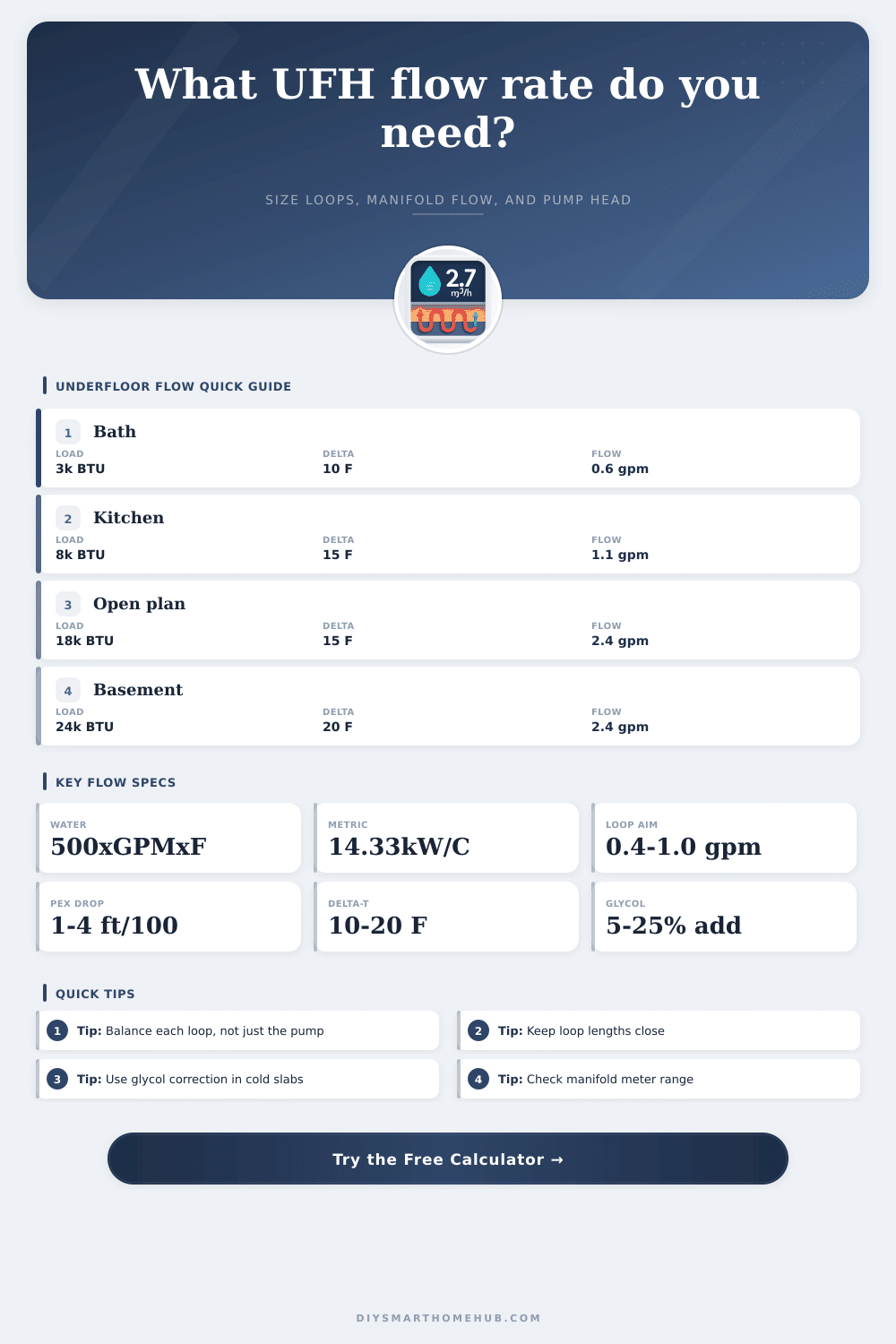
The underfloor heating system calculator will display mathematical results once you enter the heat load, desired temperature drop, number of heating loops, and pipe detail. Each of these factors impact the flow rate that determines whether each heating loop operate within its designed parameter. The heat load is the amount of energy that the underfloor heating system must emit.
The temperature drop of the water, also called the Delta-T, is the temperature that the water will drop between when it enter and exits the underfloor system. Glycol percentage determine the amount of heat that the underfloor system can carry; glycol mixtures carry less heat than plain water. Therefore, if the system use glycol, the flow rate will have to increase to carry the same amount of heat.
Pipe size and loop length will impact the head pressure drop that the underfloor system create. Head pressure drop is the amount of pressure that the circulator pump must exert to push water through the underfloor system’s pipes. Loop length and loop spacing will also impact the underfloor heating system.
Closer spacing between the heating pipes allow more pipe per square foot of floor area. Additionally, closer spacing between the heating pipes can reduce the amount of water that the underfloor heating system must reach the floor with. However, the closer that the heating pipes are placed to each other, the higher the friction rate within the system.
Longer underfloor heating system loop will reduce the number of connections between each loop at the manifold. However, the longer the underfloor heating system loops are, the higher the resistance that the pump must overcome to move the water through the system. The underfloor heating system calculator can display this information for you to help you decide whether to add more heating loop or shorten the length of the underfloor heating system’s loops.
Manifold flowmeters will be used to measure the flow of water through each heating loop of the underfloor heating system. Each of these flowmeters will have a range within which they can measure the flow of water. If the flow rate of the water in each of the underfloor heating system’s heating loop is outside of the flowmeters’ measuring range, the flowmeters will not provide you with accurate measurement of the flow through each loop.
Additionally, the velocity of the water within each loop is another factor to consider. If the velocity at which the water travel through each loop of the underfloor heating system is too high, it will create noise within the system and cause the erosion of the walls of the metal pipe. Too low a velocity of water travel within the underfloor heating system will allow air to remain within the pipes.
This will make it difficult to balance the underfloor heating system. You want to control the flow and ensure that the velocity of the water remain within the recommended band for the specific tubing that the underfloor heating system use. Not all room within a building have the same heating requirements.
This is due to the different material that are used to build each room. For instance, a bathroom that has tile will have a different heating requirement than a room that has a thick concrete slab. The temperature drop that is set for a space with tile may have to be lower than the temperature drop for the concrete slab.
Heat pump will have lower supply temperatures for the radiators than underfloor heating systems will. Lower supply temperatures will require a higher flow rate. Retrofit system that use underfloor heating system components within joist bay will have lower efficiency than underfloor heating systems that are installed on new concrete slab.
The retrofit system will have to reach the same result with a higher water temperature or have the heating pipes placed closer to the floor. Once you have the target flow that the calculator determined for each heating loop, you must go to the manifold to set the flow for each loop. Each flowmeter should be set to the target flow that was calculate for each of the heating system’s heating loops.
Fine tune this setting by checking the return temperature from each of the heating system’s loops or by measuring the amount of time that it take for the room to reach the desired temperature. If the flowrate for each of the heating system’s heating loop is colder than the others, increase the flowrate for that heating loop. If the flowrate for each of the heating system’s heating loop reaches a temperature that is warmer than the other heating loop, throttle the flow for that heating loop.
It will take some time to balance each heating loop proper. Underfloor heating system pump do not have to overcome the resistance of each heating loop at the same time. The pump only has to overcome the resistance of the most restrictive heating loop and the fitting within the system.
Adding up the length of each heating loop will not result in an accurate calculation of the head pressure that the pump must exert to push water through each loop. Underfloor heating system calculator will estimate what the head of each pump should be to overcome the resistance of the most restrictive underfloor heating system loop. This will help you select a circulator pump that can vary the speed at which water is push through each heating loop.
An underfloor heating system is consider to be successful if each loop of the system reaches the same temperature in each room and if the pump is not working too hard to circulate the water. Factors such such as flow rate per loop within the range of the flowmeters, water velocity within the system, and the head pressure requirement of the pump will determine whether the underfloor heating system is successful. Additionally, as these factor approach their ideal setting, the underfloor heating system will be easier for you to balance.
The underfloor heating system calculator will make it easier for you to reach these setting.