TV Antenna Range Calculator
Estimate free-space path loss, line-of-sight reach, field strength, and tuner noise margin for over-the-air TV reception before you choose an indoor, attic, or rooftop antenna strategy.
| Band | Typical RF Range | Center Frequency | Planning Note |
|---|---|---|---|
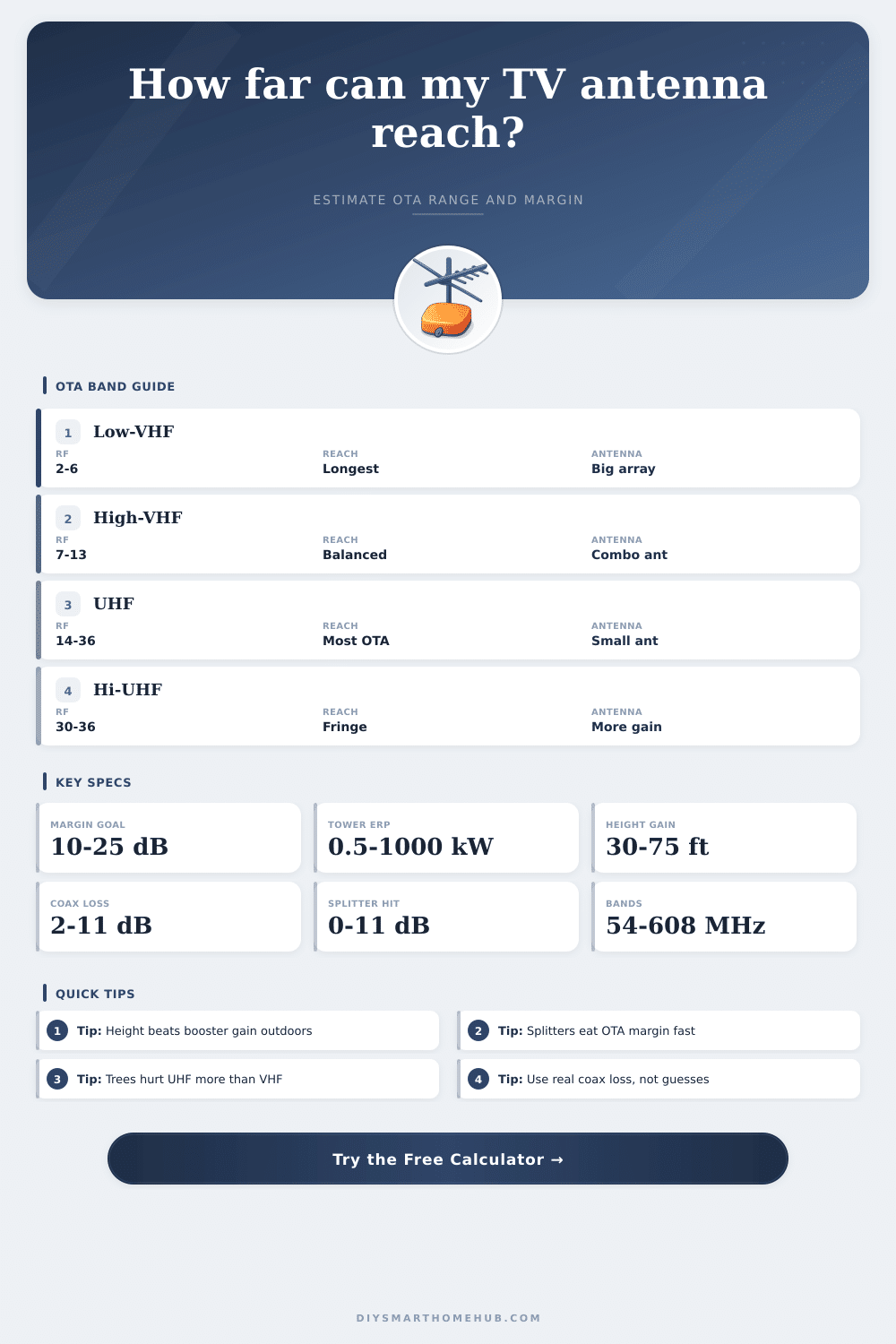
| Low-VHF | RF 2-6 | 54-88 MHz | Longest wavelength and biggest antennas, but often excellent diffraction over distance. |
| High-VHF | RF 7-13 | 174-216 MHz | Balanced reach with manageable antenna size and better clutter tolerance than UHF. |
| UHF | RF 14-36 | 470-608 MHz | Most OTA channels live here, but every wall, tree, and coax foot matters more. |
| Hi-UHF edge | RF 30-36 | 566-608 MHz | Fringe stations at the top of UHF usually demand the cleanest cable and best aim. |
| Profile | Nominal Gain | Best Bands | Typical Use |
|---|---|---|---|
| Indoor Flat UHF | 2 dBi | Strong UHF | Window placement near metro towers with minimal coax and no splitter. |
| Attic Combo | 6 dBi | High-VHF + UHF | Suburban homes where the roof adds some shielding but tower paths stay moderate. |
| Roofline Yagi | 10 dBi | High-VHF or UHF | Outdoor mast installs that need more directivity and cleaner multipath control. |
| 8-Bay Bowtie | 12 dBi | UHF | Longer UHF paths when width and gain matter more than low-band coverage. |
| Deep Fringe Combo | 14 dBi | High-VHF + UHF | Remote rooftops chasing weak clusters with minimal splitter use and careful aiming. |
| Low-VHF Array | 8 dBi | Low-VHF | Large-element arrays for the rare low-band station or long analog-style path. |
| Component | Low-VHF | High-VHF | UHF / Note |
|---|---|---|---|
| RG-59 per 100 ft | 1.8 dB | 3.0 dB | 5.6 dB at 600 MHz |
| RG-6 per 100 ft | 1.2 dB | 2.1 dB | 3.9 dB at 600 MHz |
| RG-11 per 100 ft | 0.8 dB | 1.4 dB | 2.6 dB at 600 MHz |
| 2-way / 4-way / 8-way | 3.5 dB | 7.0 dB | 11.0 dB worst case split |
| Scenario | Path Distance | Likely Antenna | Planning Read |
|---|---|---|---|
| City apartment window | 5-15 mi | Indoor flat | Usually fine if towers are strong and the window faces the market. |
| Suburban attic install | 20-35 mi | Attic combo | Height and roof composition decide whether attic works or rooftop wins. |
| Roof mast single TV | 30-50 mi | Roofline Yagi | Strong option when splitters stay low and the horizon remains open. |
| Fringe rural cluster | 45-70 mi | Deep fringe combo | Needs clean coax, more height, and little terrain shadow to stay reliable. |
If the receive antenna clears nearby rooflines and tree crowns better, both the radio horizon and the real clutter loss improve. Amplifiers cannot rebuild signal that never reached the antenna.
One market can mix strong UHF, moderate high-VHF, and a single fringe low-band signal. Planning around the hardest channel keeps the final antenna choice honest.
To recieve over-the-air television signals, you must understanding how signal strength and signal loss can affect your television signal reception. Many people attempt to use indoor antennas to receive over-the-air signals. However, indoor antennas often fails to deliver the signal required for television reception due to indoor antennas not having the necessary height or power to overcome the various obstacles between the television signal source and the antenna.
These obstacles can include tree, buildings, and roofs, all of which have the ability to block the television signals from reaching the indoor antenna. To receive a reliable signal from the television broadcast towers, you will have to account for the distance between those broadcast towers and your antenna, as well as a number of obstacles in the way. The type of signal being received also has an impact on your television signal reception.
Why Indoor Antennas Lose TV Signal and How to Fix It
Common television signals includes high-VHF signals and UHF signals. However, trees and walls are more likely to block UHF signals then high-VHF signals. UHF signals have shorter wavelength than high-VHF signals.
These shorter wavelengths cause UHF signals to scatter when they encounter obstacles like leaves and walls. Therefore, the UHF signal may weaken before it reach your indoor antenna compared to the VHF signal, even though the broadcast tower may be close to your home. Another factor that will affect the signal that your indoor antenna receives is its physical height.
Increasing the height of your indoor antenna will help it to receive the television signal. Increasing the height of your indoor antenna will allow your antenna to clear the local horizon. By clearing the local horizon, your indoor antenna will be able to avoid both local noise and physical obstacle in its path to the television signal source.
If you place your indoor antenna at a low height, it will struggle to receive the signal from sources that may be blocked by trees or hills. Therefore, you should focus on increasing the height of your indoor antenna to ensure that it has a clear path to the broadcast tower. Coaxial cable, or coax cable, will cause a loss of the television signal as it travels from the antenna to the television.
The longer your coaxial cable, the more loss of signal strength occur in your television signal. This loss of signal strength is referred to as attenuation. If you utilize less expensive coaxial cable, such as RG-59 cable, you will lose more signal strength than if you used higher quality coax cable, such as RG-6 cable.
Additionally, if you use splitters to distribute the signal from your antenna to multiple room in your home, you will experience a loss of signal strength with each splitter. If you have too many splitters in your television signal path, your signal may become too weak for your television tuner to decode the signal. The terrain on which your antenna is positioned will also impact the signal strength that reaches your indoor antenna.
For instance, if your indoor antenna is located in a suburban area with many tree, you may find that the tree branches block the UHF signals from reaching your indoor antenna. In rural areas, hills may block the signal from reaching your indoor antenna. If you live in a valley, the valley walls may block the signal from the broadcast tower.
Since terrain can impact signal strength, you should position your indoor antenna based off the weakest signal received in your area. The weakest signal may be a channel using low-VHF or high-UHF frequencies. The signal strength of this channel will determine the size of the antenna that you need for reliable reception.
To receive television signals effectively, aim for a specific noise margin. The noise margin is the difference between signal strength and the threshold of signal strength the television tuner requires to decode the signal. Aim for a noise margin that is fifteen decibel above the threshold that your television tuner requires.
A fifteen-decibel margin will allow your television signal to account for signal loss caused by weather or foliage blocking the signal. If the noise margin is below ten decibels, your television signal will experience dropouts. Additionally, if the noise margin is above twenty-five decibels, your signal will remain stable, even during storms.
Finally, there are some mistake that many people make when attempting to receive over-the-air television signals. Using indoor antennas is one common mistake. Indoor antennas often do not receive signals as well as outdoor antennas because indoor antennas lose five to ten decibels of signal strength due to surrounding walls.
Another mistake is the use of too much coaxial cable and too many splitters. Too much coax cable and too many splitters will weaken the signal that reaches your television. To receive a reliable signal from over-the-air television broadcasts, you must account for the height of your antenna, the quality of your coaxial cable, and the number of splitter used in your signal path.
You should of checked these things before buying new equipment.