Sub Panel Load Calculator
Estimate subpanel demand from continuous and noncontinuous VA, convert the result to amperage, select the next standard feeder breaker, and compare headroom against the feeder and panel bus.
Calculate to compare installed feeder capacity against the adjusted load.
Continuous loads are multiplied before adding demanded noncontinuous VA.
Demand factor is applied only to the noncontinuous load portion.
Remaining amps appear after a valid load schedule is calculated.
| Standard breaker | 120/240 V 1 phase capacity | 208Y/120 V 3 phase capacity | Typical subpanel use |
|---|---|---|---|
| 30 A | 7,200 VA | 10,808 VA | Small garage, shed, lighting, limited tools |
| 40 A | 9,600 VA | 14,407 VA | Equipment rack, light workshop, office circuits |
| 50 A | 12,000 VA | 18,013 VA | Basement, detached room, small appliance mix |
| 60 A | 14,400 VA | 21,611 VA | Workshop, garage expansion, mixed branch circuits |
| 70 A | 16,800 VA | 25,216 VA | Studio, larger garage, HVAC plus receptacles |
| 80 A | 19,200 VA | 28,814 VA | EV ready area, larger detached space |
| 90 A | 21,600 VA | 32,419 VA | Kitchen remodel subpanel or dense branch circuits |
| 100 A | 24,000 VA | 36,027 VA | Small dwelling unit or high-capacity garage panel |
| 125 A | 30,000 VA | 45,034 VA | Large detached shop or three phase equipment panel |
| Load type | Common VA basis | Calculator bucket | Formula treatment |
|---|---|---|---|
| Fixed lighting that stays on | Fixture schedule VA | Continuous VA | Multiply by 1.25 before adding to demand |
| Network rack or server gear | Nameplate watts or VA | Continuous VA | Use 125% if expected to run three hours or more |
| EV charger or process load | Output amps x volts | Continuous VA | Use continuous multiplier before breaker sizing |
| General receptacle circuits | Load schedule VA | Noncontinuous VA | Apply selected demand factor if justified |
| Small shop tools | Nameplate VA or circuit estimate | Noncontinuous VA | Apply demand factor to intermittent load portion |
| Kitchen or laundry appliance | Nameplate VA | Usually noncontinuous | Use 100% unless the project load method permits demand |
| Demand factor | When it is conservative | When to avoid it | Calculator effect |
|---|---|---|---|
| 100% | Unknown mix or critical branch circuits | Rarely too conservative for planning | Counts all noncontinuous VA |
| 90% | Small panel with modest diversity | Loads likely to run together | Removes 10% of noncontinuous VA |
| 75% | Garage or shop with intermittent tools | Appliance-heavy simultaneous loads | Removes 25% of noncontinuous VA |
| 60% | Large mixed-use panel with documented diversity | Continuous or life-safety load groups | Removes 40% of noncontinuous VA |
| 50% | Concept planning only with strong diversity basis | Final feeder sizing without verification | Halves only the noncontinuous VA |
| Scenario | Input load mix | Adjusted demand | Planning cue |
|---|---|---|---|
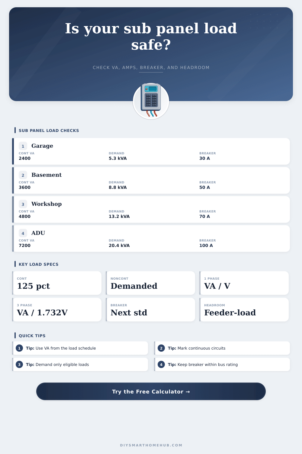
| Small garage 30 A | 1.2 kVA continuous, 3.6 kVA noncontinuous | 4.2 kVA at 75% | Comfortable on a 30 A 120/240 V feeder |
| Equipment rack 40 A | 4.8 kVA continuous, 0.8 kVA noncontinuous | 6.6 kVA at 75% | Continuous load dominates breaker size |
| Workshop 60 A | 3.6 kVA continuous, 10.8 kVA noncontinuous | 12.6 kVA at 75% | Headroom is limited on 60 A single phase |
| ADU 100 A | 7.2 kVA continuous, 15.2 kVA noncontinuous | 20.4 kVA at 75% | Fits 100 A only if demand assumptions hold |
| Three phase shop 125 A | 12 kVA continuous, 28 kVA noncontinuous | 36 kVA at 75% | Three phase voltage basis lowers feeder amps |
Keep continuous loads in their own VA bucket. The calculator applies 125% only to that bucket, so a server rack or charger does not get blended into intermittent tool or receptacle demand.
Use the smaller practical limit between the feeder breaker and the panel bus. A 100 A panel on a 60 A breaker still has a 60 A feeder limit for this planning check.
When you add a subpanel to a garage, a basement, or an accessory dwelling units, you have to make sure that the feeder can handle the electrical loads that will be added to that subpanel. The feeder itself must be large enough to handle all of the electrical loads, and it must be able to handle both continuous and noncontinuous loads. Many people makes the mistake of simply adding the nameplate numbers of all of the electrical devices that they plan to add to the subpanel.
However, adding these nameplate numbers together will give incorrect results because it does not take into account the difference between continuous and noncontinuous electrical load. For instance, if you are adding an electric vehicle charger and lights to the basement, the lights and electric vehicle charger may be running for extended period of time, and these loads could push the feeder beyond it’s capacity. An electrical load that is expected to run for three hour or more is referred to as a continuous load.
How to Size a Feeder for a Subpanel
Any continuous loads must be calculated at 125% of the actual Volt-Ampere (VA) value of the load prior to adding other electrical loads to the total. Electrical loads that are not expected to run for three hours or more is referred to as noncontinuous loads. You can apply demand factors to noncontinuous loads to account for the fact that they will not be running at maximum power simultaneously.
Thus, continuous and noncontinuous loads should be separated prior to performing any calculations regarding the electrical loads that will be added to the subpanel. In the example of the basement that is to be rewired with a subpanel, there may be recessed lights, a bath fan, and a heater in the basement. The lights and bath fan are examples of continuous loads, so you must multiply them by 1.25.
The electrical receptacles and shop tools in the basement are examples of noncontinuous loads, and those loads can be reduced via the application of a demand factor. For instance, if 75% is used as the demand factor for the tools in the shop instead of the 100% demand factor for all of the electrical loads, this will make a difference in whether a 60-amp or 80-amp breaker is needed for the basement subpanel. The breaker size is based off the calculated amperage of the electrical loads, not the total number of amps that the electrical devices will draw when they are operating.
The next size of breaker should be selected above the total calculated amperage; however, you must also compare the size of the breaker to the rating of the panel bus. For instance, if the panel bus is rated to handle 100 amps of electrical current, but the calculated amperage of the basement subpanel is 60 amps, a 60 amp breaker would be selected for the feeder. However, if the panel bus is only 60 amps, then the amperage of the feeder will be the limiting factor, and you should use a 60 amp breaker for that subpanel.
Thus, the feeder amperage must be compared to the panel bus amperage. Adding electrical loads to a subpanel after the initial calculation of the feeder can create electrical problems. For instance, if a basement subpanel is created that also includes receptacles for a dust collector and a 240-volt heater for the workshop, the power for these two receptacles are considered to be noncontinuous loads.
However, if the dust collector and the heater is expected to be operating at the same time, this could make the initial calculation based upon a demand factor incorrect. Thus, it is a recommendation to provide headroom for any future electrical loads in the subpanel to avoid having to rewire the entire subpanel. Three-phase electrical systems require different mathematical calculations than single-phase electrical systems due to the use of the square root of three in the denominator of the electrical load calculation formula.
Three-phase systems create less line current than single-phase systems if they contain the same total Volt-Amps (VA). Three-phase systems distribute the electrical load across three separate legs instead of the two legs of a single-phase electrical system. Thus, electrical calculations should include the type of electrical system that is to be created so that any calculations will automatically perform the necessary calculations to convert single phase electrical systems to three phase electrical systems (or vice versa).
Demand factors for electrical loads are percentages of the total calculated load. However, the percentage should represent the actual percentage of the electrical loads that will be used. For instance, people often apply a 75% demand factor to electrical loads in a garage.
However, a 75% demand factor assume that not all of the devices in the garage will be running at the same time. Thus, if the garage contains circuits for two different vacuum cleaners and each vacuum cleaner is expected to run constant, 75% may not be a realistic demand factor for the garage. A 100% demand factor could be used instead, though, since there is no evidence that the electrical equipment will not be running at the same time.
Finally, the limit of the panel bus must not be exceeded. The feeder and the breaker sizes may be calculated for a specific amount of amperage, but the electrical current that is created in the panels cannot exceed the panel bus rating. For instance, a main-lug subpanel may be rated at 125 amps, but it is impossible for that subpanel to exceed that 125 amp electrical current.
The electrical capacity of the feeder panel is the smaller of the two values (feeder breaker size and panel bus size). Thus, any calculations of amperage must be made certain to compare the calculated amperage to both the feeder breaker and the panel bus rating to ensure the electrical system is safe. In order to ensure that the feeder will not be the weak link in the electrical system, there are several steps that should be followed.
First, any continuous loads must be separated from the noncontinuous loads. Second, you must multiply the continuous loads by 1.25. Third, a demand factor should be selected that matches the use of the electrical equipment.
Finally, the calculated amperage should be compared to both the feeder breaker and the panel bus.