Relay Split Calculator
Estimate how smart relay loads should be divided across channels by voltage, watts, inrush, relay rating, module derating, grouping, and spare capacity.
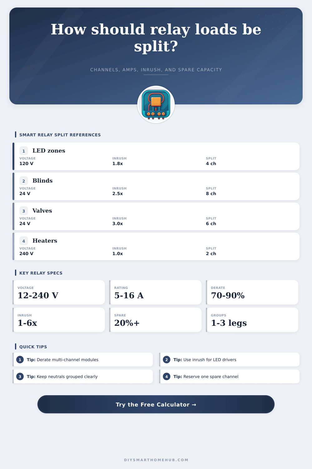
▣Real smart relay presets
⚙Load and relay inputs
▦Calculated relay snapshot
ℹRelay split notes
▤Load type reference table
| Load type | Typical PF | Inrush range | Split behavior | Calculator use |
|---|---|---|---|---|
| LED driver lighting | 0.85 to 0.95 | 1.5× to 4× | Many small zones can exceed start current before steady current | Use listed VA or raise inrush for large driver banks |
| Resistive heat or lamps | 1.00 | 1.0× to 1.2× | Steady amps and thermal derating dominate | Keep high-duty loads below derated channel limit |
| Small motors and actuators | 0.60 to 0.85 | 2× to 6× | Start surge can force more channels or contactors | Use nameplate VA where available |
| Solenoids and coils | 0.55 to 0.80 | 2× to 4× | Short duty loads can share channels by manifold or zone | Use simultaneous duty for worst active bank |
| Electronics and plug loads | 0.70 to 0.95 | 1.5× to 3× | Power supplies may surge together after outage restore | Use a higher spare target for clustered devices |
▧Relay/channel spec comparison grid
| Relay module class | Common channels | Contact rating | Thermal total | Best matched load |
|---|---|---|---|---|
| Low-voltage DIN relay | 4 to 8 | 5 A to 8 A | 50% to 75% of channel sum | 24 V valves, dampers, shade motors |
| Lighting relay actuator | 4 to 16 | 6 A to 10 A | 60% to 80% of channel sum | LED lighting zones and small switched circuits |
| Power relay module | 2 to 4 | 12 A to 16 A | 70% to 90% of channel sum | Resistive heat zones and high-duty loads |
| Dry-contact output board | 4 to 12 | 1 A to 5 A | Often coil or signal limited | Contactor coils, alarms, automation inputs |
| Hybrid smart relay | 1 to 4 | 8 A to 16 A | Device enclosure dependent | Single-room lights, fans, and small appliances |
▨Phase and neutral grouping reference
| Grouping model | Typical use | Split target | Calculator meaning |
|---|---|---|---|
| One shared group | Single supply, one common neutral or one transformer | Evenly fill available channels | All channels are considered one balancing pool |
| Two separated groups | Two panel legs, two transformers, or two manifolds | Split channels and loads as evenly as possible | Recommendation checks channels per group |
| Three separated groups | Three zones, phases, or supply groups | Keep load count and amps close across groups | Rounding may add channels to preserve separation |
| Four separated groups | Four manifolds, rooms, or relay banks | At least one channel available per group | Flags cases where group count exceeds usable channels |
▩Common smart relay split scenarios
| Scenario | Typical load basis | Useful split | Main constraint |
|---|---|---|---|
| Kitchen LED zones | 60 W to 120 W per zone at 120 V | One or two zones per relay channel | Driver inrush at scene start |
| Eight shade motors | 12 W to 35 W per motor at 24 Vdc | One motor per output for direction control | Low-voltage supply group and start surge |
| Irrigation valves | 6 VA to 12 VA per 24 Vac coil | Group by manifold and common | Transformer VA and simultaneous valves |
| Heat mat relays | 300 W to 900 W per zone at 120/240 V | One high-duty zone per channel | Continuous thermal load |
| AV rack outlets | 100 W to 400 W per switched group | Split power supplies across channels | Restore inrush and spare capacity |
The calculator estimates electrical loading and split balance. Final hardware selection still depends on the relay datasheet, enclosure temperature, load category, and applicable electrical code.
When you are thinking about the design of an relay panel, you must consider more than the individual ratings of the relays that will be used. Many peoples focus on the capacity of the individual relays, but a person must also consider the effect that the total load will have upon the relay panel. A relay split calculator can assist in the planning of the relay panel by converting watts, amps, and inrush currents into a single value that describe the capacity of the relay panel.
Relay contacts often fail due to heat instead of overloads. The heat build up within the relay panel if the heat cannot leave the enclosure quick enough. While the specifications sheet for a multi-channel relay module may list the amperage for each of the individual channels, the total amperage that the devices that is connected to the channels draw must remain within a specific limit.
How to Plan a Relay Panel
Enter the total load, the number of channels, and the derating for the relay panel cabinet into the calculator to determine if the limit is based on the capacity of each individual channel or if it is based on the ability of the relay panel to release heat. Another factor to consider is inrush currents. Devices like LED lights and motors often draw an inrush current of between two and three times than their normal current draw at the beginning of their operation.
If a significant portion of the capacity of each channel is devoted to normal operation, the inrush current of the devices may exceed the capacity of the relay to close. Enter the inrush current into the calculator to determine if the loads needs to be distributed to additional channels or if the control of some of the devices need to be changed. Grouping is another factor to consider when wiring the relay.
Devices on different phases of the electrical circuit draw different loads from the power supply. Devices that share a neutral or low-voltage common are also grouped together. Enter the number of groups into the calculator to determine if the number of relays can support the grouping of the devices.
Do not consider each relay in a relay panel to be the same as each other; the relay panel wiring diagram will indicate the number of devices that need to be grouped together. Spare capacity can be used as a variable to determine how many devices will be added in the future. Twenty percent spare capacity is often specified as the target for the spare capacity of a relay panel.
However, this spare capacity also must account for potential errors in the measurements of current and voltage, temperature changes in the environment in which the equipment is deploy, and additional devices that may be deployed in the future. Enter these other parameters into the calculator to determine if the spare capacity of the relay panel will meet the target that is specified. You can use the reference tables when you are selecting the hardware for the relay panel before you know the loads that will be used.
One table describes the effect that inrush current have on devices within groups of devices. The other table compares relay modules based on its thermal limits. These tables are not rules that you can memorize, but they are tables that can be referenced before you order the relay modules.
Overall, rather than thinking of the selection of relays as a process that involves adding amps together to determine the total amps that the devices draw, the relay selection process is actualy one that manage the heat budget, the surge budget, and the wiring topology of the relay panel. Ensuring that the heat budget, the surge budget, and the wiring budget are respected will ensure that the relay panel does not require maintenance after the installation of the devices.