DC Power Calculator
Estimate low-voltage smart home watts, supply amps, cable voltage drop, load voltage, and daily DC energy from real device and wire values.
| Load type | Typical rail | Typical current | Power formula result |
|---|---|---|---|
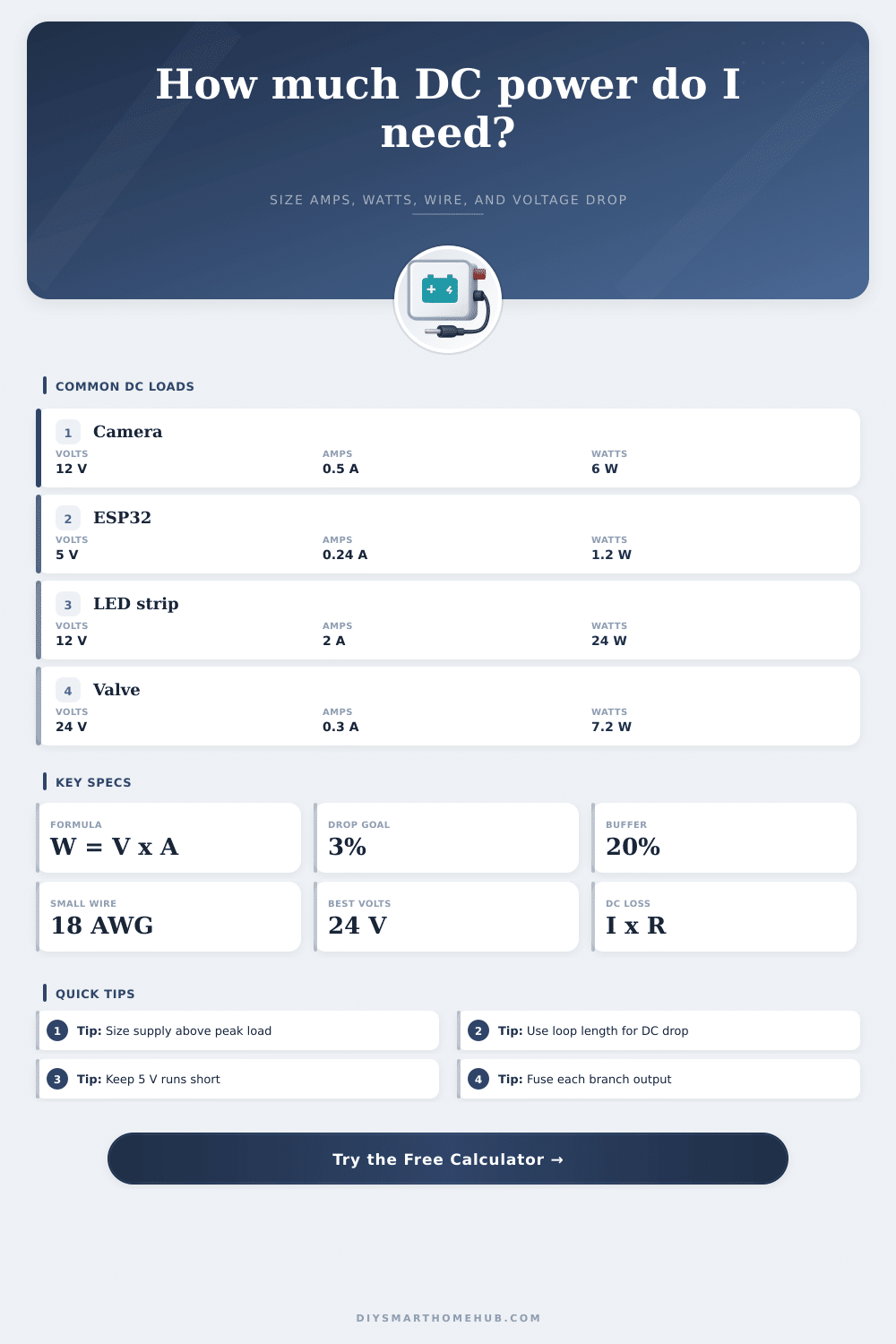
| ESP32 or small sensor board | 5 V DC | 0.16 to 0.32 A | 0.8 to 1.6 W |
| Raspberry Pi 4 automation node | 5 V DC | 1.2 to 2.5 A | 6 to 12.5 W |
| Indoor 12 V IP camera | 12 V DC | 0.35 to 0.70 A | 4.2 to 8.4 W |
| 12 V IR illuminator | 12 V DC | 0.8 to 1.5 A | 9.6 to 18 W |
| 12 V LED strip, 5 meter section | 12 V DC | 1.5 to 5.0 A | 18 to 60 W |
| 24 V smart valve actuator | 24 V DC | 0.2 to 0.5 A | 4.8 to 12 W |
| Gauge | Resistance | Drop at 2 A over 40 ft | 12 V drop percent |
|---|---|---|---|
| 18 AWG copper | 6.385 ohm per 1000 ft | 1.02 V | 8.5% |
| 16 AWG copper | 4.016 ohm per 1000 ft | 0.64 V | 5.4% |
| 14 AWG copper | 2.525 ohm per 1000 ft | 0.40 V | 3.4% |
| 12 AWG copper | 1.588 ohm per 1000 ft | 0.25 V | 2.1% |
| 10 AWG copper | 0.999 ohm per 1000 ft | 0.16 V | 1.3% |
| 8 AWG copper | 0.628 ohm per 1000 ft | 0.10 V | 0.8% |
| DC branch | Continuous load | With 20% headroom | Practical supply label |
|---|---|---|---|
| Three 12 V cameras at 0.5 A | 1.5 A / 18 W | 1.8 A / 21.6 W | 12 V, 2 A minimum |
| One 5 V Pi node at 1.8 A | 1.8 A / 9 W | 2.16 A / 10.8 W | 5 V, 2.5 A minimum |
| Two 12 V LED strips at 2 A | 4 A / 48 W | 4.8 A / 57.6 W | 12 V, 5 A minimum |
| Four 24 V valve actuators at 0.3 A | 1.2 A / 28.8 W | 1.44 A / 34.6 W | 24 V, 1.5 A minimum |
| Router and modem on 12 V rail | 3 A / 36 W | 3.6 A / 43.2 W | 12 V, 4 A minimum |
| Project | Example load | Calculated power | Wire planning note |
|---|---|---|---|
| Single room sensor cluster | 4 ESP32 boards, 5 V | 4.8 W at 0.96 A | Short 5 V runs reduce brownouts |
| Front door camera and access | Camera plus controller, 12 V | 14.4 W at 1.2 A | 14 AWG helps on longer door runs |
| Kitchen cabinet lighting | Two LED strip sections, 12 V | 48 W at 4 A | Feed strips from both ends if needed |
| Garage automation panel | Relay board and sensors, 12 V | 11 W at 0.92 A | Fuse branch circuits separately |
| Whole hub backup rail | Router, modem, hub, Pi, 12 V | 54 W at 4.5 A | Use larger wire for long battery runs |
When you are first beginning to wire smart home device, it is natural to feel that the power flowing through the low voltage lines isnt an immediate concern. It is common for people to find that the camera and LED strips that are purchased will show up and work proper when they are first plugged in. However, problems may develop in some of these devices after a period of time has passed.
Problems with the camera may manifest themselves as the camera needing to reboot during cold weather. Problems with the LED strips may be that the LED strips begins to dim along their wire runs. Both of these problems can be avoided if the person is knowledgeable about the factors that relate to and impact low voltage DC circuit.
How to Check Voltage Drop in Smart Home Wiring
Thus, prior to wiring in any device, the person should become knowledgeable about each of the factors that will impact voltage drop along the circuits created by those device. The calculator that is provided on the page require that the person inputs certain number related to the devices and the wires that will be used to create the circuits. Each of these factors has a specific meaning and impact on the calculation that the calculator will provide.
For instance, the supply voltage is the voltage that is printed on the power supply device, but it is not the same than the voltage that will be supplied to the devices along the circuit. The current that each device pulls when it is activated (such as when a motor is spinning or a radio signal is transmitted) is the current that should be used in the calculation. The length of the cable should be the one-way distance from the power supply to the end of the wire run, as the electricity will travel in both direction along the wire.
The gauge of the wire can be any gauge that is used for the devices, but the resistance of the wire will impact voltage drop along the wire run. One of the most important variables to consider in these circuits is the drop in voltage along the wire run. For example, if the camera that is utilized requires a 12-volt power supply, but it is only receiving 10.8 volts, the camera may still function.
However, if the voltage drop is too great for a device like an ESP32 that requires 5 volts, the device may not boot up proper. For this reason, it is common for the percentage of voltage drop to be the key measurement of voltage drop calculations. A percentage drop in voltage of 3% is common for home automation device, as this 3% voltage drop allows for for voltage drops that may result from temperature changes in the automation system.
The calculator can show the number of volts that will be dropped along the wire run, the percentage of voltage drop along that wire, and whether or not that voltage drop is acceptable for the specific device that is being create. In addition to the calculations that the calculator presents, it is also important to provide headroom for the power supply for the devices. Thus, in addition to calculating the current that the devices will draw, 20% extra capacity should be provided to that calculated value to allow for headroom for devices starting up.
This headroom will allow for more current to be provided to these devices during their startup periods (when devices like motors, LED lights, or radio devices draw the most current), and will prevent the power supply from overheating. Another factor that should be considered when creating a circuit is the duty cycle of the devices and the amount of energy that they will use each day. For instance, an LED strip that is only activated four hours per night will use a different amount of energy each day than a security camera that remains on for 24 hours per day.
The calculator provided can calculate the total energy in watt-hours that the devices will use per day by multiplying the total wattage of the devices by 24 hours and the percentage of duty cycle. The result will be provided in amp-hours, which can then be compared to the capacity of any battery that is to be used in the automation smart home device. In the real world, the voltage drops and power calculations will not always be the same as those that are indicated on the device datasheet.
For instance, voltage drops due to temperature changes in the circuits can change the resistance of copper wire that are used in the circuits. In addition, the resistance of the electrical connections can also impact the voltage drops along the wire runs. Thus, it is recommended that the developer uses the calculations provided by this calculator as a starting point in creating the smart home devices.
Furthermore, if the voltage drop that is calculated is near 5%, it may be easy to solve the problem by changing the size of the wires that are use. Another decision that will need to be made is whether the devices will utilize 12-volt DC power rails or 24-volt DC power rails. For example, if higher voltages are used, the current that is required to power the devices will be lower.
Lower currents will result in a lower voltage drop along the power cables. Thus, using 24 volts rather than 12 volts will provide advantage in power distribution if the length of the wires is greater than 30 feet. For shorter distances, such as within a home, using 12 volts or 5 volts will make it easier for the devices to be manufactured with the voltages that are required by the devices.
These two voltage options can be compared within the calculator by changing the supply voltage that is selected. Most people make mistakes when setting up their smart home when they treat the DC circuits as if they were AC circuits. For instance, the electric company maintain the voltage in AC circuits.
In low-voltage DC circuits, each individual developer and builder are responsible for every component of the circuit. Furthermore, if the return wires are not of sufficient size (or if they are shared with other circuits), the devices will behave in an unpredictable fashion. To avoid these types of issues, dedicated power and return wires can be used for each device, and the return wires of each device can be connected to a proper power distribution block.
The reference tables that are provided on this page will help the developer to understand what voltages and currents are typical in smart home devices. For example, the reference tables indicate the current that draws devices such as security cameras, magnetic relay boards, and LED light section. Furthermore, another reference table indicates the voltage drops that occur along wires of different gauges over a 40-foot distance.
This information can help a developer understand, for instance, the difference in voltage drops of using 18 AWG wire versus 14 AWG wire for the smart home devices. Once the developer has entered the information regarding the devices and the circuits, these factors will become more easily understood. The developer will understand whether a single power supply is enough for each branch of devices, whether individual regulation of the devices will be necessary, whether the energy use of the circuits will be within the capacity of the battery, and whether the calculated voltage drop will be acceptable for the devices.
Overall, the developer will understand the information necessary to create a circuit that maintains a stable voltage drop for all device in both extreme hot climates and extreme cold climates.