Single Phase Arc Flash Calculator
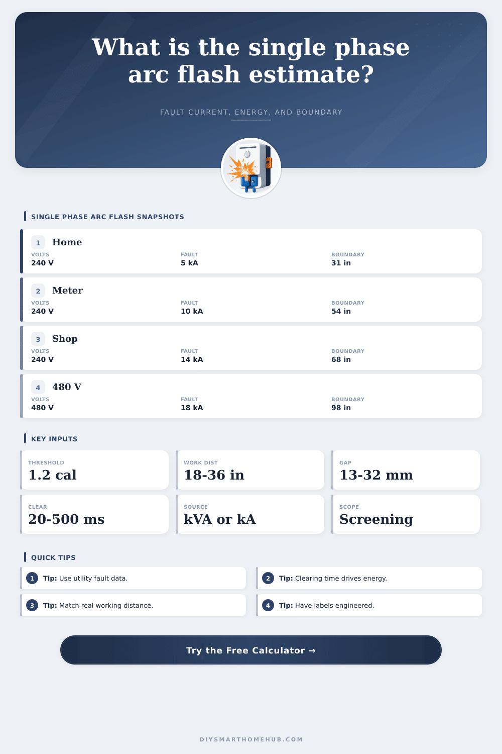
Estimate single-phase bolted fault current, arcing current, incident energy, arc flash boundary, and clearing-time sensitivity for panelboards, meters, disconnects, and small distribution gear.
1.Single-phase panel presets
2.Fault source and arc inputs
Single-phase arc flash screening result
Enter inputs and calculate to see the estimated incident energy and boundary.
3.Single-phase equipment/spec grid
4.Reference tables
| Single-phase equipment | Typical voltage | Working distance | Useful input to verify |
|---|---|---|---|
| Residential service panel | 120/240 V | 18 in | Utility fault current and breaker curve |
| Meter socket / service base | 120/240 V | 12-18 in | Service transformer kVA and impedance |
| Garage or outbuilding subpanel | 120/240 V | 18 in | Feeder length, conductor size, OCPD curve |
| Fused disconnect | 240 or 480 V | 18-24 in | Fuse class and clearing time at arcing current |
| Control power panel | 208, 277, or 480 V | 24-36 in | Transformer impedance and enclosure depth |
| Energy band | Incident energy | Boundary behavior | Planning note |
|---|---|---|---|
| Below threshold | Under 1.2 cal/cm2 | Boundary is inside working distance | Still evaluate shock and task risk |
| Low | 1.2 to 4 cal/cm2 | Boundary extends outside work position | Confirm with formal study before work |
| Moderate | 4 to 8 cal/cm2 | Boundary grows quickly with time | Review clearing time and maintenance mode |
| High | 8 to 25 cal/cm2 | Large boundary possible | Engineering controls should be considered |
| Extreme | Over 25 cal/cm2 | Very large boundary possible | Do not use this screening tool for decisions |
| Transformer | 240 V full-load amps | 2.5% impedance fault | 4.0% impedance fault |
|---|---|---|---|
| 15 kVA | 62.5 A | 2.5 kA | 1.6 kA |
| 25 kVA | 104 A | 4.2 kA | 2.6 kA |
| 50 kVA | 208 A | 8.3 kA | 5.2 kA |
| 75 kVA | 313 A | 12.5 kA | 7.8 kA |
| 100 kVA | 417 A | 16.7 kA | 10.4 kA |
| Input | Low value effect | High value effect | Why it matters |
|---|---|---|---|
| Clearing time | Less exposure energy | Energy rises nearly linearly | Protective device curve often dominates |
| Working distance | Energy increases sharply | Energy drops with distance squared | Use the real task posture distance |
| Fault current | May extend clearing time | May trip devices faster | Always pair current with trip curve data |
| Gap/enclosure | Less concentrated estimate | More concentrated estimate | Box geometry changes worker exposure |
5.Practical tips
Electricians will tell you they’ve done this before: assumed that a panel was single-phase, and therefore assumed it was safe. After all, there’s no three-phase raw driving force that causes those hair-raising arcs in industrial switchgear. Sure, you open the door, change out the breaker, and assume worst case is not a flash fire but just a really bad shock. Well, that’s where they gets themselves in trouble. Even with single-phase, arcs can delivers severe burns and beyond if fault current is high enough and the clearing device doesn’t trip for even a fraction of a second. Sometimes it comes down to milliseconds of sustained energy exposure.
This means plugging your numbers into the calculator above (it takes care of the math for you based off your custom system configuration) without having to make up coefficients that vary depending on gap size and voltage. The single most important number here is typically clearing time, as incident energy increase almost directly proportional to time. A lot of people will consider the bolted fault current and stop there, but remember you’re doubling your exposure if an arc persists for 200 milliseconds vs. 100. It is a simple relationship but have significant consequences.
Why Single-Phase Panels Can Still Be Dangerous
Because arcs can reduce current flow enough to prevent an instantaneous trip of a breaker, it’s important to know what happens to protective device curve at estimated arcing current, not just the bolted. Secondly, working distance also plays an important role (most of us reach into a panel from approximately 18 inches away). The amount of energy that reaches your face is inversely proportional to the distance between you and the hazard, and it do so dramatically; energy level decreases by the square of the distance! Just moving a few inches away will make a huge difference in exposure levels, but you can’t always move back while holding a screwdriver inside a live enclosure. In this case, knowing where boundary is is critical. Even if you believe you’re being extra-careful, you’ll still be in the danger zone if the arc flash boundary exceeds where you would normally stand.
Geometry factors such as what sort of enclosure is used also comes into play: How much thermal energy can reach the working person depends on the size of the physical space surrounding the arc. A shallow box concentrates heat different than an open rack or a deep meter socket. This is one variable that’s easy to forget, yet can significantly change result.
Next, the distance between conductors (perhaps only 13 millimeters in a tightly packed residential panel) are close enough for an arc to bridge easily when faulted. While a greater distance makes it harder to ignite, it doesn’t necessarily make resulting arc less severe.
Additionally, note that the impedance of the transformer itself set the stage (a lower-impedance transformer will pump more current to a fault). This results in faster clearing times for some devices and longer sustained energy for others. It is an all-or-nothing tradeoff based solely on your actual protective coordination. If you have knowledge of your true source impedance, don’t depend on defaults, use nameplate info or utility data for a far more accurat picture of the true risk.
To conclude. This isn’t meant to replace a properly engineered study but instead is a tool for spotting potential issues before they occur. A good example would of seeing that a boundary exists on a panel that will encroach upon the work space. Seeing those numbers raise red flags, then it’s time to have a pro come out and give it the complete treatment.
The point of all this safety stuff is not just assuming you’ll be okay and crossing your fingers, it’s understanding where the boundaries are and not crossing the line. Walk away from each project with both skin and confidence still intact.