Refrigerant Line Charge Calculator
Estimate added line charge by liquid line factor, compare it with theoretical line inventory, and roll the result into total system charge for split, heat pump, or rack branch runs.
📌Field Presets
⚙Line Charge Inputs
How to use it: the rule-based added charge uses excess liquid line length beyond the factory included run, while the theoretical line inventory uses actual inside diameter, temperature, and fill assumptions for a second check.
Charge Summary
Run a calculation to compare manufacturer style added charge with line inventory mass.
📊Selected Refrigerant Snapshot
R-410A
At 95 F
Selected liquid line factor
Included liquid line
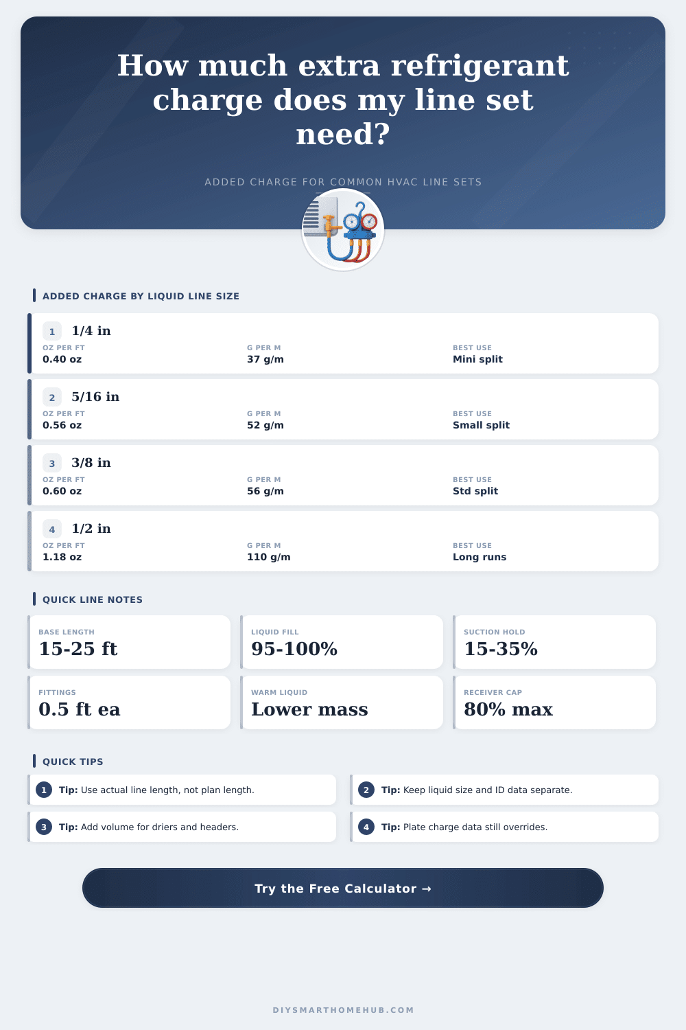
📏Added Charge Factor Table
| Liquid Line Size | Added Charge | Metric Rule | Common Application |
|---|
📐Approximate Tube Volume Table
| Approx ID | in3 per ft | L per m | Typical Role |
|---|
📘Refrigerant Density Reference
| Refrigerant | 40 F Density | 100 F Density | Safety | Common Use |
|---|
📋Common Line Set Scenarios
| Scenario | Included Length | Likely Add Rule | Why It Changes |
|---|
Tip: If the equipment is precharged for 15 feet but your liquid line equivalent length is 42 feet after fittings, charge by the 27-foot excess, not just the straight tape measurement.
Tip: Large suction headers and branch manifolds can hold more refrigerant than the liquid line rule suggests, so compare the rule-based add charge against the theoretical line inventory before final weighing.
When installing a new line set for either a heat pump or a condenser, teh amount of refrigerant that must being added to the system needs to be calculated. The amount of refrigerant that is required to be added to the system is dependent upon the length of tubing that will extend beyond the amount of refrigerant that the manufacturer provided as a factory charge for the system. If there is too little refrigerant provide to the system, the system will experience a starvation of refrigerant, which will lead to an increase in the superheat levels of the refrigerant.
Conversely, if there is too much refrigerant added to the system, the evaporator may flood with refrigerant, or the refrigerant may flood back into the compressor. Thus, it is necessary for the technician to accurately calculate the amount of refrigerant that will be required to be added to the system in order to ensure that the system operate correctly. Manufacturers typically indicate the amount of refrigerant that should be provided to the system at the factory in the unit itself.
How to Calculate the Right Amount of Refrigerant
The factory charge indicates the amount of refrigerant that should be provided to the system with the manufacturer’s factory charge with a length of tubing that is typically 15 foot in length. In most cases, the refrigerant lines that is provided to the HVAC system will have elbows, traps, and headers that will extend the length of the tubing beyond the 15 feet of tubing. Such an extension in length is referred to as the equivalent length of the tubing for those specific fitting.
For instance, a 90-degree elbow may be considered as equivalent to half a foot of tubing. Thus, if the length of the refrigerant lines is not accounted for in the addition of the refrigerant that is to be provided, the system will experience an addition of an incorrect amount of refrigerant. Within the nameplate of the HVAC system, the manufacturer will indicate the rule for the addition of refrigerant to the system.
The rules indicate the amount of ounces of refrigerant that should be provided to the system for each foot of excess line. The amount of refrigerant that should be added to the system will vary according to the size of the liquid line and the type of refrigerant that is provided for that HVAC system. For instance, if the size of the liquid line is 3/8-inch in diameter, 0.60 ounces of refrigerant R-410A may be added for each foot of tubing.
However, if the size of the liquid line is 1/2-inch in diameter, 1.18 ounces of refrigerant R-400A may be added for each foot of tubing. Thus, the larger the diameter of the liquid line, the more refrigerant that should be provided. Additionally, each type of refrigerant has a different density.
Thus, different amounts of refrigerant will be required to fill each of these lines of different diameters. Another element to consider for the HVAC system is the length of the suction line. The suction lines contain refrigerant in the form of vapor rather than liquid.
Consequently, the suction line will not be completely filled with the refrigerant in liquid form. For instance, the amount of liquid that will remain in the suction line will be between 15 and 35 percent full. If the size of the suction line is too large, the system may experience a refrigerant pooling issue for the suction line.
The refrigerant may pool in the suction line in the liquid form, which will reduce the capacity of the HVAC system. If the size of the suction line is too small for the system, the suction line may become a restriction to the movement of the refrigerant in the system. This restriction may lead to a refrigerant pressure drop in the system.
The theoretical calculations of the amount of refrigerant that is to be provided to the HVAC system can be determined through the calculation of the size of the inside diameter of the tubing. The formula for volume is the inside diameter times pi times the radius squared, multiplied by the length of the tubing. This calculated volume can be converted to a value in terms of the total amount of mass of refrigerant by utilizing the density of that refrigerant at the current ambient temperature.
The density of the refrigerant will vary with the temperature of the HVAC system; thus, a density value that is appropriate for the temperature of the system environment should be used. This calculated mass value can be multiplied by a safety margin. For instance, a 95 percent fill factor can be applied to the total amount of liquid refrigerant.
Additionally, a 25 percent factor can be applied to the amount of suction refrigerant. These factors will ensure that the calculations is accurate for the HVAC system. The amount of refrigerant that is to be provided to the system as indicated by the rules on the nameplate can be compared to the amount of refrigerant that was calculated using the theoretical calculations.
If the refrigerant amount indicated by the rules for the system is similar to the theoretical calculation of the amount of refrigerant that should be provided, then the total amount of refrigerant that is provided to the HVAC system is likely accurate. If the amount indicated by the rules on the nameplate differs from the theoretical calculation of the amount of refrigerant for the system by 20 percent or more, then it is necessary to use a scale to measure the amount of refrigerant that is to be provided. Using a scale is the most accurate means of providing the amount of refrigerant to the system.
Finally, it is necessary to record these measurement in the notes that are written for that HVAC system; these notes will assist in any future visit to provide service to that system.