💨 PSI to CFM Calculator
Calculate airflow through orifices, valves & compressors for smart home pneumatic and HVAC systems
⚙️ Airflow Calculator
⚡ Quick Presets
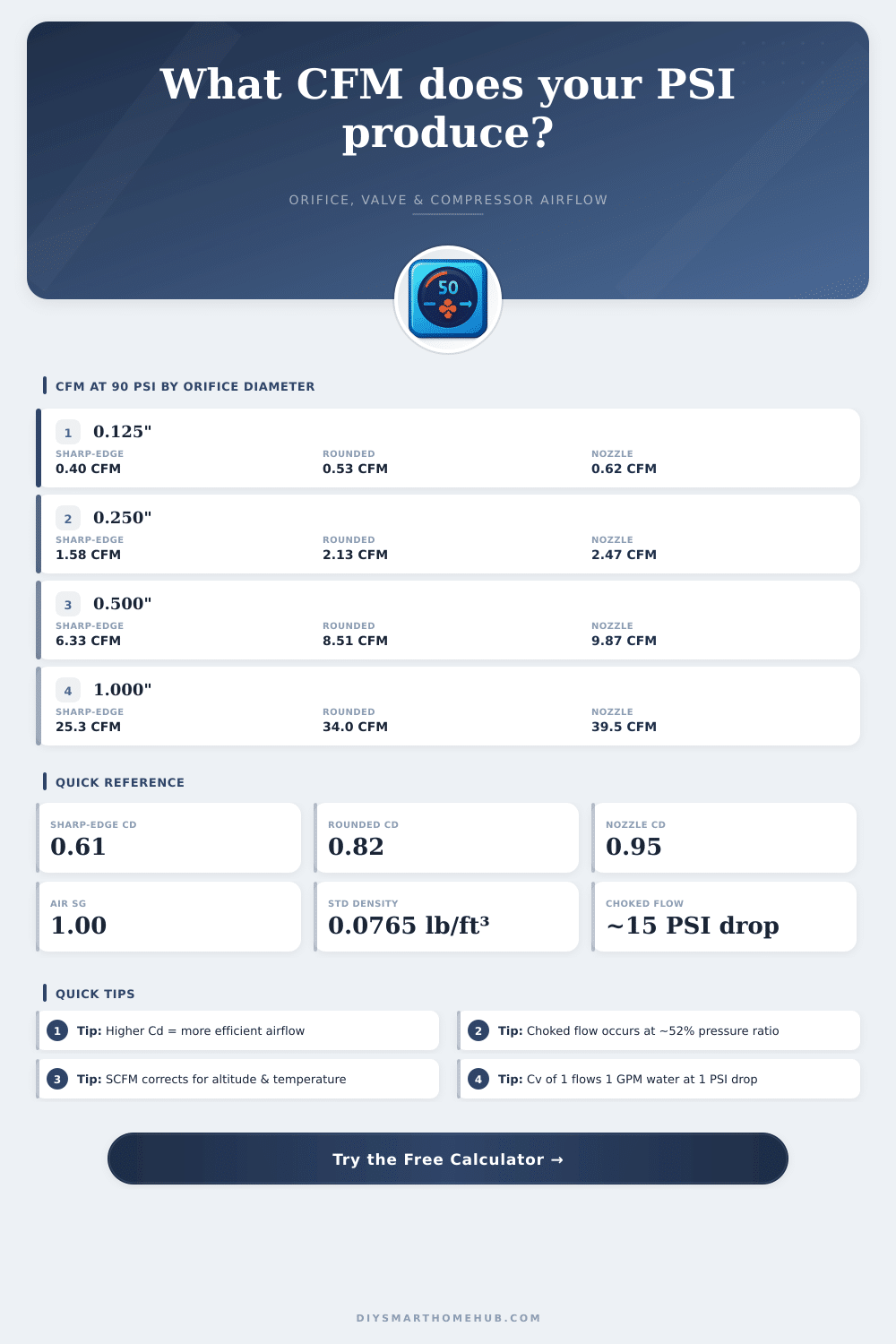
📊 Spec Grid — CFM at 90 PSI by Orifice Size
| Orifice Dia (in) | Area (in²) | Sharp-Edge Cd=0.61 | Rounded Cd=0.82 | Nozzle Cd=0.95 | Velocity (ft/s) Sharp |
|---|---|---|---|---|---|
| 0.0625 | 0.00307 | 0.10 CFM | 0.13 CFM | 0.15 CFM | 548 |
| 0.125 | 0.01227 | 0.40 CFM | 0.53 CFM | 0.62 CFM | 548 |
| 0.1875 | 0.02761 | 0.89 CFM | 1.20 CFM | 1.39 CFM | 548 |
| 0.250 | 0.04909 | 1.58 CFM | 2.13 CFM | 2.47 CFM | 548 |
| 0.375 | 0.11045 | 3.56 CFM | 4.79 CFM | 5.55 CFM | 548 |
| 0.500 | 0.19635 | 6.33 CFM | 8.51 CFM | 9.87 CFM | 548 |
| 0.750 | 0.44179 | 14.24 CFM | 19.13 CFM | 22.19 CFM | 548 |
| 1.000 | 0.78540 | 25.32 CFM | 34.03 CFM | 39.47 CFM | 548 |
📈 Pressure vs CFM Table (Sharp-Edge Cd=0.61)
| Pressure (PSI) | 0.25in Orifice | 0.50in Orifice | 1.00in Orifice | Flow Regime |
|---|---|---|---|---|
| 40 | 1.05 CFM | 4.22 CFM | 16.87 CFM | Subsonic |
| 50 | 1.18 CFM | 4.71 CFM | 18.85 CFM | Subsonic |
| 60 | 1.29 CFM | 5.17 CFM | 20.67 CFM | Subsonic |
| 70 | 1.39 CFM | 5.58 CFM | 22.32 CFM | Subsonic |
| 80 | 1.49 CFM | 5.96 CFM | 23.83 CFM | Subsonic |
| 90 | 1.58 CFM | 6.33 CFM | 25.32 CFM | Subsonic |
| 100 | 1.67 CFM | 6.67 CFM | 26.70 CFM | Subsonic |
| 110 | 1.75 CFM | 7.00 CFM | 27.99 CFM | Subsonic |
| 120 | 1.83 CFM | 7.31 CFM | 29.25 CFM | Subsonic |
🚰 Valve Cv Flow Table — CFM at Various Pressures
| Cv Value | 10 PSI drop | 30 PSI drop | 60 PSI drop | 90 PSI drop |
|---|---|---|---|---|
| 0.1 | 1.86 CFM | 3.22 CFM | 4.55 CFM | 5.57 CFM |
| 0.5 | 9.30 CFM | 16.10 CFM | 22.76 CFM | 27.87 CFM |
| 1.0 | 18.60 CFM | 32.21 CFM | 45.52 CFM | 55.74 CFM |
| 2.0 | 37.19 CFM | 64.42 CFM | 91.04 CFM | 111.48 CFM |
| 3.0 | 55.79 CFM | 96.63 CFM | 136.56 CFM | 167.22 CFM |
| 5.0 | 92.98 CFM | 161.04 CFM | 227.60 CFM | 278.71 CFM |
| 7.0 | 130.18 CFM | 225.46 CFM | 318.64 CFM | 390.19 CFM |
| 10.0 | 185.97 CFM | 322.09 CFM | 455.20 CFM | 557.42 CFM |
* Cv formula: CFM = Cv × 18.597 × sqrt(ΔP / SG). Air SG = 1.0 at standard conditions.
When selecting solenoid valves or pneumatic actuators for smart home automation, always calculate required CFM at minimum supply pressure. A valve rated at 90 PSI may deliver 30–40% less flow at 60 PSI. Use Mode B to correct compressor output across pressure ranges, and add a 20% safety margin to all flow calculations for real-world fitting losses.
Air flow through an orifice becomes choked (sonic) when downstream pressure drops below approximately 52% of absolute inlet pressure — roughly a 15 PSI differential at 30 PSIA inlet. At choked conditions, increasing differential pressure no longer increases flow. For HVAC dampers operating below 2 PSI differential, subsonic equations apply and small pressure changes produce linear CFM changes, making Cv-based sizing ideal for zone control valves.
When you buy air compressor, you commonly hear about PSI and CFM, both are important. The thing is, they measure entirely different parts of how a compressor works. PSI shows the pressure of the air while CFM shows the amount of air that moves in a minute.
If you mix them, you risk choosing the wrong tool for the task
What PSI and CFM Mean for Air Compressors
PSI measures pounds per square inch, so it shows pressure. It says how much force pushes on every square inch. So 100 PSI means 100 pounds per square inch.
The compressors must stay in specific ranges to work well, to go outside them can cause touble or even damage.
Here comes the hard part. You cannot simply convert PSI to CFM, no matter how you try. They deal with pressure against volume.
You could compress one cubic foot of air to 1 PSI, or 30 cubic feet to same pressure. Trying to change them is like trying to put square feet in a round hole. It simply does not work.
Here happens reverse relation. In higher PSI, the CFM drops. For instance, industrial rotary screw compressors measure 100 CFM at 100 PSI.
Alter the pressure up or down, and the CFM follows. For best information, measure the CFM in your work area. Practically, around 4 to 5 CFM match to real horsepower.
There is yet something important: CFM measures free air delivery. Note the difference between SCFM and ACFM. SCFM stays in standard conditions…
14.7 PSI atmospheric pressure, 68°F and 36% humidity. ACFM instead takes the real circumstances under that you use the machine.
The build matters. Two-stage models reach higher pressure, while the piston size causes the CFM output. Air tools work best at 90 PSI.
For instance, spray guns work in 24 to 32 PSI for good coats, but require around 15 CFM here. Air tools consume 5 to 6 CFM at 90 PSI. 60-horsepower unit gives about 150 CFM, while 150-horsepower reaches almost 2000 CFM.
You can use formula. CFM matches tank capacity in gallons times 0.536, times gauge pressure, divided by fill time in seconds. Pipe diameter affects.
For choosing right tube, you require your CFM flow and pipe length, wider tubes move more air. The nozzle and fixtures also alter the output, so even mighty compressor will not give the same through small tube with tiny fittings. Thenozzle and fixtures also alter the output, so even mighty compressor will not give the same through small tube with tiny fittings.