PoE Voltage Drop Calculator
Estimate how much voltage arrives at the endpoint after copper resistance, service slack, and maximum PoE load so your cameras, access points, and controllers stay inside a safe operating window.
| Endpoint | Max Draw | Min Input | Coverage | Best Fit |
|---|
| Source | Nominal V | Powered Pairs | PD Limit | Use Case |
|---|
| Cable | Resistance | Comfort Run | Drop Bias | Note |
|---|
| Scenario | Endpoint | Source | Count | Device V |
|---|
One-way run should follow the actual structured cabling path, then include patch leads and a little service slack before you judge voltage drop.
A cable run can look fine until radios, IR LEDs, or PTZ motors pull the endpoint closer to maximum draw and push voltage lower.
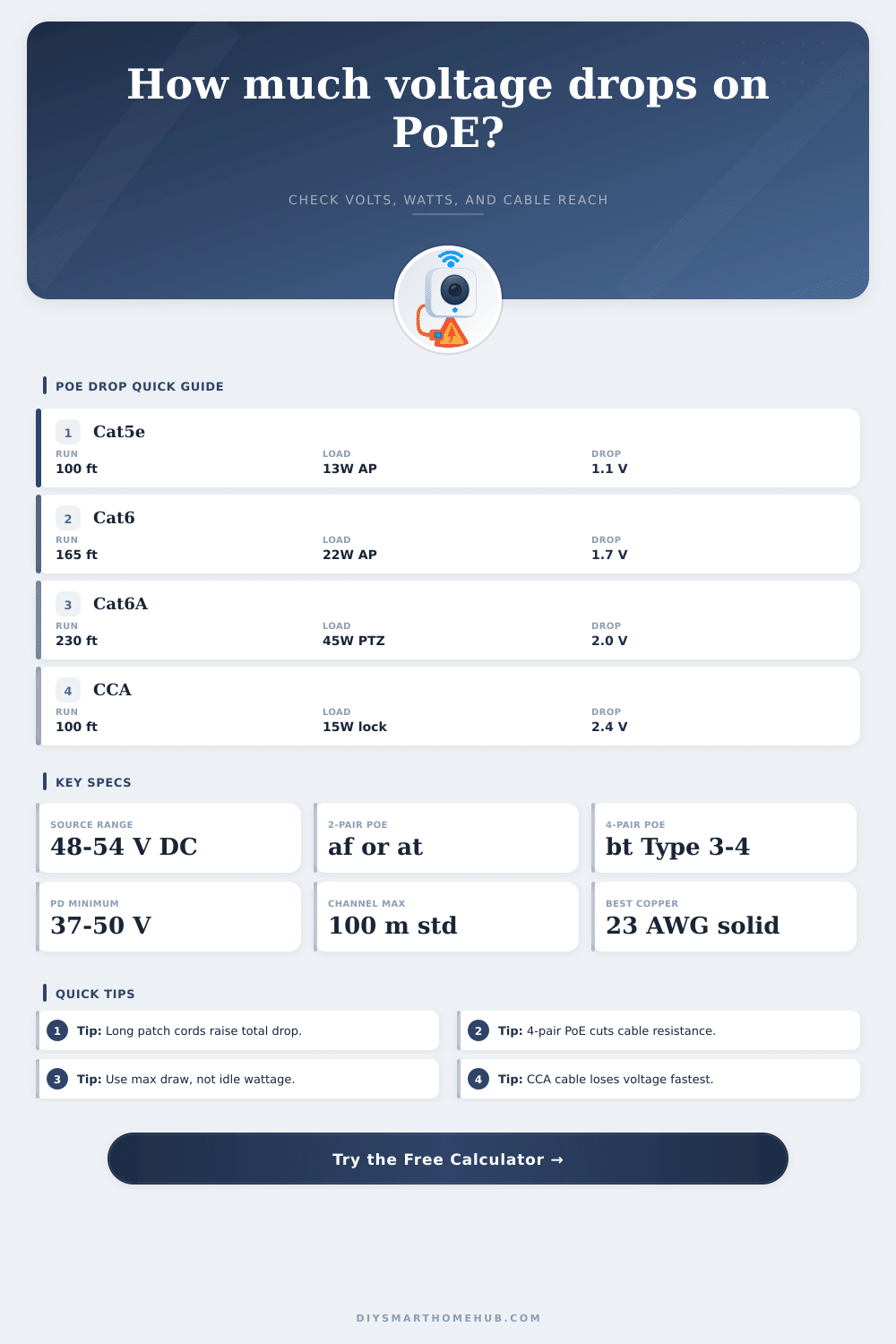
Voltage drop are one of the common problem associated with PoE installations. The reason for voltage drop is because of the resistance that the electricity encounter as it moves through the Ethernet cable. Every device that is connected to the network require a certain amount of voltage in order to function proper.
If the voltage drop to a level that the device requires to perform it’s functions, then the device will reboot or it will fail to perform its function altogether. This typically happen when the device reaches the maximum level of power draw that it can produce. For example, security camera system may draw more power when using infrared light to spotlight objects at night.
Why PoE Voltage Drops and How to Fix It
Another of the causes of voltage drop is resistance. The longer the Ethernet cable is, the more the electricity passing through the cable will encounter resistance. Additionally, the resistance will be even more if the Ethernet cable is thin in size or made up of low-quality material.
All copper materials will resist the passage of electricity, which will create heat as a result of such resistance. Because all Ethernet cable contain copper materials, the installer must account for the voltage drop when the Ethernet cable is laid out for installation. The use of copper clad aluminum (CCA) Ethernet cables is common because they are inexpensive.
However, CCA cables has higher resistance compared to cables made of solid copper. Thus, CCA cables will cause a voltage drop that is more significant than solid copper cables. The gauge size of the Ethernet cable pose another critical factor in causing voltage drop.
The gauge size refers to the thickness of the copper wire in the cable. The lower the gauge number, the thicker the cable wire will be. Thick copper cables has less resistance in their wires.
For instance, 23 AWG cables are thicker than 24 AWG cables. This mean that 23 AWG cables will have less voltage drop along the cable than 24 AWG cables. Using Cat6 or Cat6A cables with solid copper cores will allow the network device to experience less voltage drop than if it use Cat5e cables or patch cords.
Patch cords often use stranded copper wire instead of solid copper wires. Stranded wires have higher resistance properties than solid copper wires. Therefore, they will cause more voltage drop than solid copper cables.
Another of the factor that will impact the voltage drop is the PoE standard that will be used in the installation. Some PoE standards will use only two of the four pair of wires in the Ethernet cable to transmit power to the network device. Other standards will use all four pair of wires in the Ethernet cable to transmit power.
Using the four pair of wires will distribute the electrical current across more conductors in the cable. Distribution of electrical current across more conductors will reduce the resistance in the cable. If resistance is reduced, voltage drop will also be reduced.
Thus, the network device will receive more voltage from the PoE switch or injector. The power requirement of the network device must match with the PoE switch or injector to avoid dropping the voltage to a level that is less than the minimum voltage that the device requires to operate. When planning the installation, you must calculate the total length of the Ethernet cable.
However, some extra length must be allowed for service slack. Service slack is the length of Ethernet cable that is provided as extra to allow for the terminations of the Ethernet cable at the devices and switches into which it will be installed. Thus, some extra length should of been bought in to allow for slack.
The length of the cable should be planned for the maximum power draw of the network device instead of the average power draw. This is because the power draw of the device will reach a maximum during certain task. For example, a PTZ network camera will draw more power when moving it’s lens to a specific area than while viewing a static area.
Thus, the voltage drop will be more significant when the device is performing that task with maximum power draw. If you are experiencing voltage drop in an existing installation, there are several step that you can take to fix this problem. You can upgrade the Ethernet cable to one with a thicker gauge.
Additionally, you can simply replace the existing Ethernet cable with a solid copper cable. Another of the solution is to change to a PoE standard that utilize four pair of wires to carry the electrical current. Finally, if any of the above solution are not possible, installing a PoE injector will increase the voltage from the PoE switch or injector to a level that the network device can reach.
This measurement should be taken while the network device is under full load to ensure that the voltage that it recieve from the PoE switch or injector stays within the minimum voltage requirements for the device. If the voltage is only measured while the device is idle, it will drop to a level below the minimum voltage requirement once the device begin to draw maximum power from the PoE switch.