Max Fault Current Calculator
Build a maximum available fault-current envelope from utility strength, transformer impedance, feeder impedance, motor contribution, X/R ratio, and equipment ratings.
⚡Maximum fault scenarios
🔧Source and feeder inputs
📊Source and equipment grid
📋Conductor impedance reference
| Profile | Resistance | Reactance | Maximum-current note |
|---|---|---|---|
| Copper bus duct | 0.012 ohm/1000 ft | 0.018 ohm/1000 ft | Very short runs keep available fault high. |
| 500 kcmil copper | 0.0258 ohm/1000 ft | 0.030 ohm/1000 ft | Common low-impedance service feeder input. |
| 350 kcmil copper | 0.0367 ohm/1000 ft | 0.032 ohm/1000 ft | Moderate voltage drop and fault-current damping. |
| 4/0 copper | 0.0608 ohm/1000 ft | 0.035 ohm/1000 ft | Branch distribution runs noticeably reduce maximum kA. |
| 500 kcmil aluminum | 0.0424 ohm/1000 ft | 0.030 ohm/1000 ft | Higher resistance reduces available current faster. |
| 350 kcmil aluminum | 0.0605 ohm/1000 ft | 0.032 ohm/1000 ft | Use actual installed raceway geometry where available. |
🧮Formula table
| Item | Formula used | Output | Why it matters |
|---|---|---|---|
| Utility source | Zutility = VLL squared / MVA | Ohms | Models the maximum utility contribution as a Thevenin source. |
| Transformer source | I = FLA / Zpu | kA | Estimates transformer-limited maximum secondary current. |
| Minimum impedance | Ztotal = Zutility + Ztransformer + Zfeeder | Ohms | Lower impedance produces the maximum available fault current. |
| Conductor reduction | Zfeeder = length x R/X x reduction | Ohms | Accounts for cold conductor or lower-than-table impedance. |
| Motor addition | Imotor = FLA x multiplier x decay | kA | Motors can backfeed the first cycles of a fault. |
| Peak current | Ipeak = Isym x sqrt(2) x (1 + e^(-pi/XR)) | kA peak | Connects X/R ratio to peak withstand checks. |
🔌Equipment rating comparison
| Equipment point | Common rating band | Use calculator result | Review trigger |
|---|---|---|---|
| Residential main | 10 kA to 22 kA | Compare symmetrical kA to marked AIC. | Margin below 10% or unknown utility data. |
| 208V panelboard | 10 kA to 42 kA | Check panelboard and breaker series rating. | Transformer upgrade or shorter feeder. |
| 480V switchboard | 35 kA to 65 kA | Check line side, main, and feeder devices. | Parallel transformers or stiff utility source. |
| MCC bus | 42 kA to 100 kA | Include motor contribution and SCCR. | Large connected motor group on same bus. |
| Switchgear | 65 kA to 100 kA | Compare RMS and peak withstand values. | High X/R or current-limiting assumptions. |
🗂Scenario reference table
| Scenario | Voltage | Transformer | Default rating | Envelope emphasis |
|---|---|---|---|---|
| 480V service | 480 V | 1500 kVA, 5.0% | 65 kA | Utility plus transformer maximum contribution. |
| 208V panel | 208 V | 75 kVA, 2.8% | 22 kA | Small transformer with low impedance tolerance. |
| 480V MCC | 480 V | 2000 kVA, 5.5% | 65 kA | Motor backfeed included in the maximum case. |
| Long feeder | 480 V | 750 kVA, 5.2% | 35 kA | Conductor impedance trims available kA. |
| Data center PDU | 415 V | 2500 kVA, 5.0% | 100 kA | Short bus and high utility MVA drive peak current. |
💡Calculation tips
To safely size all of your equipment, you have to determine the max possible fault current. That’s the upper limit on any device rating. It depends on feeder length, transformer impedance, and utility strength. Why? Because we want our circuit breaker not to blow up because it wasn’t rated high enough.
It is important to know how strong your connection with power company is. How much can they throw at you? Get the max short-circuit MVA at service point from your provider. The higher that number is, the stiffer the source (meaning less upstream impedance). The higher the number, the higher the downstream fault currents. Guessing low here are bad. You’ll be better off assuming a stiff grid than sizing down too much.
How to Find Max Fault Current for Safety
Then there’s the transformer itself. How many times have we heard someone quote nameplate impedance but never checked the tolerance? The impedance of a transformer can be as much as fifteen percent above or below the stated rating. To calculate maximum fault current, you’ll need the lowest available impedance. So take the minimum side off the tolerance on the nameplate percentage. In other words, if your transformer is listed at 5%, you’d subtract five percent to get three percent. Lower impedance translate into higher current on a fault.
Enter the transformer size and low side of its impedance range into the calculator, and it will add in power company contribution to determine the theoretical maximum at the secondary terminals.
The other factor is direction of current flow. As it moves down from the source, there is impedance added by feeder cables and busways. The farther away you get from the source, the less fault current you’ll have. A copper bus duct has very low impedance. Over short distances, they hardly affect fault levels at all. Aluminum cable in PVC conduit presents resistance. That resistance eats into potential energy. If you’re sizing breakers on a distant subpanel, not taking that conductor drop into consideration could mean overspending. You may purchase a twenty-two-kiloamp breaker when a ten-kiloamp will do.
Don’t neglect the motors: At the beginning of a fault, induction motors serves as generators and will dump stored kinetic energy back into the bus while slowing down. Depending on the horsepower loads, they can contribute several thousand amps. These are not accounted for in the symmetrical current calculation which only considers the source. You can account for this with the calculator. It’s an important adjustment if you have motor control centers or panels feeding large machines. Otherwise, you are blinded to what level of stress these breakers is actually experiencing.
Lastly, consider asymmetry. If a fault hits right when voltage crosses zero, it will be symmetrical. That almost never happens though. Instead it will hit somewhere randomly along the waveform and therefore create an offset current. As X/R increases the severity of this offset increase. In high X/R systems, the offset is huge and results in incredibly high peak currents which stress the mechanical withstand limits of your equipment. Even if your breaker has sufficient interrupting capacity to handle the symmetrical current, its mechanical withstand capability can be exceeded by the peak force.
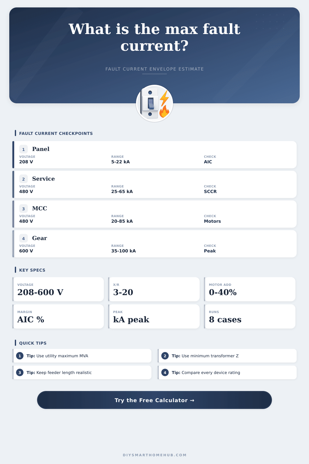
Now look at what’s rated on nameplate of the piece of gear you bought. Does it match? Did each component in the chain make it through? A 10kA breaker won’t work if your math say the max fault is 30 kA, unless it is part of a series-rated system checked by an upstream protector. People often overlook that there are multiple levels to consider. Review all of them. The reference tables has handy bands for comparing common residential mains to switchgear, which gives you a quick sanity check.
Preparing for faults seems silly. After all, we’re talking about a disaster that never actualy occurs. However, this is true insurance against chaos. If one of those bolts of lightning lands on the line or a cable melts, you don’t want a stream of shrapnel, you want the hardware to shut off the flow. Knowing your limits and having the breaker hold up shouldn’t of been about perfection. It’s about getting the numbers right.