Inverter Efficiency Calculator
Estimate how hard an inverter works at a real backup load, including idle overhead, cable loss, battery current, surge margin, and the battery capacity needed for your runtime target.
📌Scenario Presets
Each preset loads realistic values for inverter class, battery voltage, cable gauge, ambient temperature, and load pattern so you can compare runtime penalties instead of only headline efficiency.
🔌Inverter Inputs
⚙Topology Spec Grid
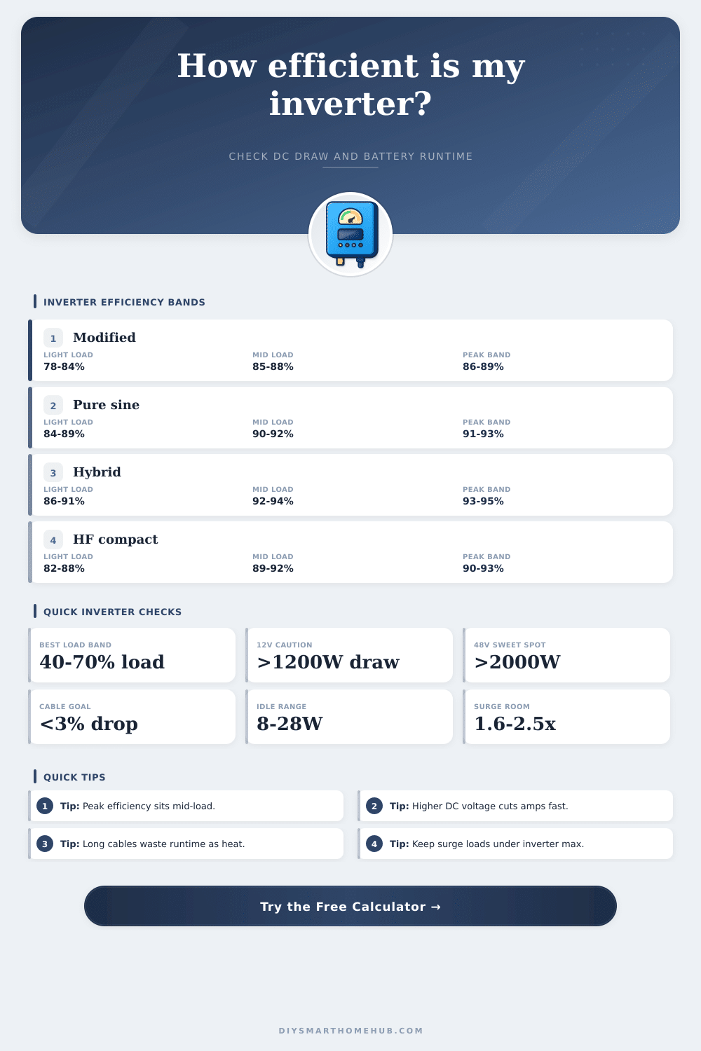
Usually the weakest at light load, but still common for simple resistive or motor tasks with generous surge room.
Most home backup loads land here when the inverter runs near 40% to 70% of its rated continuous output.
Light loads can waste a surprising share of runtime when standby draw is large compared with the AC load itself.
Startup-heavy appliances need enough burst output to clear inrush without tripping protection or sagging the battery.
Moving the same wattage to a higher-voltage battery bank sharply reduces current and cable heat.
Battery-to-inverter cables that stay below roughly three percent voltage drop preserve runtime and reduce stress.
Enclosure temperature above room conditions slowly drags efficiency down and can chip away at burst performance.
Many inverter designs reach their best real conversion zone when the load is neither too tiny nor too close to full rating.
Efficiency Band Reference
These bands help explain why the same inverter can look efficient on a label yet waste more runtime when it only powers a tiny load.
| Inverter type | 10% load | 50% load | 80% load |
|---|---|---|---|
| Modified sine | 80% | 87% | 88% |
| Entry pure sine | 85% | 91% | 92% |
| Premium pure sine | 88% | 93% | 94% |
| Solar hybrid | 89% | 94% | 95% |
Battery Current by Load
Continuous current climbs quickly on low-voltage battery banks. This table assumes roughly 90% inverter efficiency with minimal cable loss.
| AC load | 12V bank | 24V bank | 48V bank |
|---|---|---|---|
| 300 W | 27.8 A | 13.9 A | 6.9 A |
| 600 W | 55.6 A | 27.8 A | 13.9 A |
| 1200 W | 111.1 A | 55.6 A | 27.8 A |
| 2400 W | 222.2 A | 111.1 A | 55.6 A |
Surge Headroom Guide
Use a bigger margin for inductive loads. Compressors, pumps, and microwave magnetrons often need more headroom than resistive heaters or LED lighting.
| Load type | Typical surge | Suggested margin | Notes |
|---|---|---|---|
| Router and modem | 1.0x-1.1x | 10% | Very light startup event |
| TV and receiver | 1.2x-1.4x | 20% | Capacitor inrush matters |
| Fridge or freezer | 2.0x-3.0x | 35% | Compressor startup pulse |
| Sump pump | 2.5x-3.5x | 40% | High inrush and wet duty |
Common Backup Projects
Reference these project sizes when you want a quick sense of whether a battery bank or inverter class feels proportionate for the load.
| Project | Load | Best voltage | Focus |
|---|---|---|---|
| Networking shelf | 40-120 W | 12 V | Minimize idle draw |
| Sleep essentials | 80-180 W | 12 V or 24 V | Long overnight runtime |
| Kitchen cold storage | 150-350 W | 24 V | Surge margin first |
| Whole cabin circuit | 900-1800 W | 48 V | Lower current and heat |
An oversized inverter can post impressive peak specs yet run inefficiently on a tiny standby load because its idle overhead becomes a bigger slice of the battery draw.
If your backup plan climbs past a few hundred watts for long runtimes, stepping from 12 volts to 24 or 48 volts usually saves more runtime than chasing a tiny efficiency gain.
This calculator estimates inverter behavior with realistic efficiency curves, idle consumption, cable resistance, and enclosure temperature penalties. Confirm exact surge limits and standby draw from your inverter's own spec sheet before final sizing.
An inverter take the direct current (DC) from the battery and changes it to alternating current (AC) to power the appliances. Many peoples believe that an inverter maintain a constant efficiency rate. However, an inverter dont maintain a constant efficiency rate.
An inverter is most efficient when the power loads is between 40 and 70 percent of the rated output of the inverter. If the power load is too low, the inverter will consume the battery when idling. If the power load is too high, the inverter will generate heat and lose efficiency.
What Affects Inverter Efficiency
Additionally, the power load being too high for the inverter to handle will decrease the efficiency of the system. The topology of an inverter determine how the inverter process the electricity that passes through it. There are three main types of inverters: modified sine wave inverters, pure sine wave inverters, and low-frequency inverters.
Modified sine wave inverters is used for tools with high starting currents, but they may not provide the proper power for electronic devices. Pure sine wave inverters provides smooth alternating current that is suitable for devices that is sensitive to the quality of power. Pure sine wave inverters, however, have higher stand-by power draws then modified sine wave inverters.
Low-frequency inverters are better at handling high inrush currents than high-frequency inverters. Inrush currents occurs when devices such as refrigerators and sump pumps starts to turn on. The type of cable that is connect to an inverter is another critical component.
The cable gauge must be correct to ensure that the inverter operates at maximum efficiency. Thick cables has low resistance; however, the longer the cable, the higher the resistance. High resistance in a system can cause voltage sag, which will reduce the runtime of the battery.
Another factor to consider are the voltage of the battery bank. 12-volt batteries require more current then 48-volt batteries to provide the same amount of power. Higher currents creates more heat in the system than lower currents.
The temperature at which the inverter is operating can also play a critical role in how the device operates. If the enclosure in which the inverter is house reaches too high of a temperature, the inverter will derate; meaning it will produce less power. High temperatures in the system increase the resistance of the cables connect to the inverter.
High resistance in the cables reduce the efficiency of the inverter system. Additionally, another factor to consider is the depth of discharge for the batteries in the system. Lead-acid batteries should only be discharged to 50 percent to ensure there longevity.
Lithium batteries can be discharged to 90 percent. To determine the runtime of an inverter, you will have to determine the energy target for the appliances. The energy target is found by multiplying the wattage of the appliances by the number of hours that they will be on.
To find the total DC power that will be needed from the battery, you will have to include the energy losses due to the inverter and the cables that carry the power to the inverter in the equation. An inverter with a high peak efficiency may not be efficient if the inverter is not within the range of power load at which it is the most efficient. For this reason, the power load to the inverter should be adjusted to ensure that the inverter produces the maximum amount of useable energy from the battery.