Grounding Electrode Conductor Size Calculator
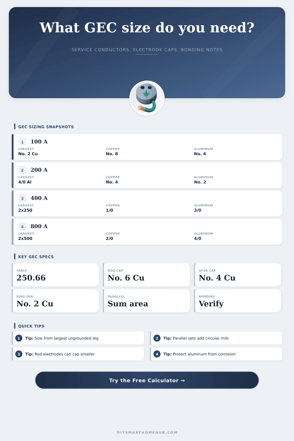
Estimate NEC-style grounding electrode conductor size from the largest ungrounded service conductor, parallel service sets, conductor material, and electrode-specific caps.
⚡Service and grounding presets
📐Calculator inputs
Estimated grounding electrode conductor
Choose inputs and calculate to see the conductor recommendation.
🧾Grounding conductor spec grid
📊NEC-style 250.66 threshold table
| Largest ungrounded service conductor | Equivalent copper area | Equivalent aluminum area | Copper GEC | Aluminum GEC |
|---|---|---|---|---|
| No. 2 copper or smaller | Up to 66,360 cmil | Up to 105,600 cmil | No. 8 copper | No. 6 aluminum |
| No. 1 through 1/0 copper | 66,361 to 105,600 cmil | 105,601 to 167,800 cmil | No. 6 copper | No. 4 aluminum |
| 2/0 or 3/0 copper | 105,601 to 167,800 cmil | 167,801 to 250,000 cmil | No. 4 copper | No. 2 aluminum |
| Over 3/0 through 350 kcmil copper | 167,801 to 350,000 cmil | 250,001 to 500,000 cmil | No. 2 copper | 1/0 aluminum |
| Over 350 through 600 kcmil copper | 350,001 to 600,000 cmil | 500,001 to 900,000 cmil | 1/0 copper | 3/0 aluminum |
| Over 600 through 1100 kcmil copper | 600,001 to 1,100,000 cmil | 900,001 to 1,750,000 cmil | 2/0 copper | 4/0 aluminum |
| Over 1100 kcmil copper | Over 1,100,000 cmil | Over 1,750,000 cmil | 3/0 copper | 250 kcmil aluminum |
🧲Grounding electrode type cap table
| Electrode type | Common cap or minimum | Calculator behavior | Planning note |
|---|---|---|---|
| Rod, pipe, or plate | No larger than No. 6 copper or No. 4 aluminum | Caps the table result when selected | Supplemental electrode rules may still apply |
| Concrete-encased electrode | No larger than No. 4 copper | Caps copper at No. 4 and aluminum at No. 2 equivalent | Often called a Ufer electrode |
| Ground ring | Not smaller than No. 2 copper | Raises copper recommendation to No. 2 minimum | Ring conductor itself has its own minimum |
| Metal water pipe or full GES | Use table 250.66 style sizing | No cap applied | Bond interior metal piping as required |
| Combined electrodes | Most demanding connected electrode governs | Shows cap note and bonding reminder | Use the conductor path serving all electrodes |
🔁Parallel sets and conductor area examples
| Service example | Selected conductor | Parallel sets | Equivalent area | Likely copper GEC |
|---|---|---|---|---|
| 200 A dwelling | 4/0 aluminum | 1 | 211,600 cmil | No. 4 or capped by electrode |
| 320 A meter main | 350 kcmil aluminum | 1 | 350,000 cmil | No. 2 copper |
| 400 A service | 250 kcmil aluminum | 2 | 500,000 cmil | No. 2 copper |
| 600 A service | 350 kcmil aluminum | 2 | 700,000 cmil | 1/0 copper |
| 800 A service | 500 kcmil copper | 2 | 1,000,000 cmil | 2/0 copper |
🧰Copper and aluminum GEC quick reference
| GEC material | Smaller table outputs | Larger table outputs | Use note |
|---|---|---|---|
| Copper grounding electrode conductor | No. 8, No. 6, No. 4, No. 2 | 1/0, 2/0, 3/0 | Common for service grounding electrode runs |
| Aluminum grounding electrode conductor | No. 6, No. 4, No. 2, 1/0 | 3/0, 4/0, 250 kcmil | Needs corrosion and termination review |
| Copper-clad aluminum service conductors | Use aluminum column for largest conductor basis | Follow terminal markings | Calculator treats this as aluminum basis |
| Bonding jumpers | May share sizing basis | May differ by location | Main bonding jumper and supply-side bonding have separate rules |
✅Grounding sizing tips
When you’re building out and an inspector flags one of those wires in your service panel because “you forgot to ground it,” you don’t often think that grounding has anything to do with current carrying capacity or voltage. But that is usually not true. The grounding electrode conductor (GEC) isn’t meant to be a power line; it’s intended as kind of safety tether. It carry a fault current safely away from danger.
To ensure correct sizing of this conductor, you need to match its size to that of the main service entrance conductors serving your business or home. Enter details of your conductors into the calculator above and math will get done for you. You won’t have to look up table numbers in the NEC and then cross-reference the area in circular mils.
How to Choose the Right Grounding Wire Size
It’s a pretty basic concept that people sometimes get wrong: According to the National Electrical Code (NEC), when sizing a grounding electrode conductor, they don’t look at anticipated load or breaker ampacity. They examine physical cross-sectional area of your biggest ungrounded service-entrance conductor. Why? Because if you’re getting some serious main feeder coming into your house, you want a nice solid way back out. Picture a big pipe, and you need a strong drain line to match. It is kind of like matched set. Identify what is there instead of guessing how much it might carry.
Parallel conductors throw a monkey wrench into the calculations as well. To manage big loads with reasonable-sized wiring, many electrician run more than one set of wires, and they may even do so side by side in parallel. For example, in a case with two sets of 500 kcmil copper, you can’t simply look at one wire to determine what size ground is needed. You need to sum the circular mils for all ungrounded conductor in that set. The reference table on the page will show you how that translates into equal-sized grounding wires. As long as you account for these areas, the grounding path will be proportional to total amount of current carried by all the conductors in your service entrance.
Beyond price, material selection makes a difference. For example, copper is readily available and straightforward. Aluminum costs less and weighs less for big production runs of commercial applications. You can select aluminum vs. Select copper in the calculator to make an even comparison. Keep in mind that aluminum does have different expansion/contraction traits as compared to copper and will require attention to termination methods and corrosion protection. Using wrong crimping method with aluminum grounding conductors is a classic recipe for failure down the road. The antioxidant must also be specified properly; otherwise, the connection will fail. Aluminum isn’t bad, it just needs respect when being installed.
Your sizing is capped by something called electrode caps. Depending on what type of ground electrode you use (a Ufer electrode embedded in the concrete around a home’s perimeter or a direct connection to a metal water pipe), the code sometimes limit your grounding conductor to a specific size. This limit applies regardless of how large your service conductors are. Even if you have a giant industrial feed, it may be capped off at a number 6 copper GEC if you’ve got a rod electrode.
This is done because once you start pushing too much fault current through too small of an electrode, you get less benefit and run the risk of creating stray voltage problems for neighboring properties. That’s why your number stops increasing when you increase your main wire size, even though this seems counter-intuitive. The calculator takes care of all those capping rules for you.
The other piece many of us overlook is physical protection. If you’re installing electrical in an exposed area like a basement or garage, you must protect the grounding conductor from physical harm (typically by rigid tubing or steel conduit). Did you crush the wire during a remodel? Did you nick it with a drill bit? You’re now without your life-saving tether. These installation conditions are flagged by the calculator and remind you to consider physical protection before pulling the wire.
But in the end, it’s all about resiliency and redundancy: having a good earth ground. It needs to be something that withstands any worst-case electrical failure without breaking, melting or dissapears. That last step of connecting to the earth should of be big enough for what comes through from your primary conductors. Match those up correctly and you have a system that can deal with the unexpected when it knocks on your door.