Ground Wire Size Calculator
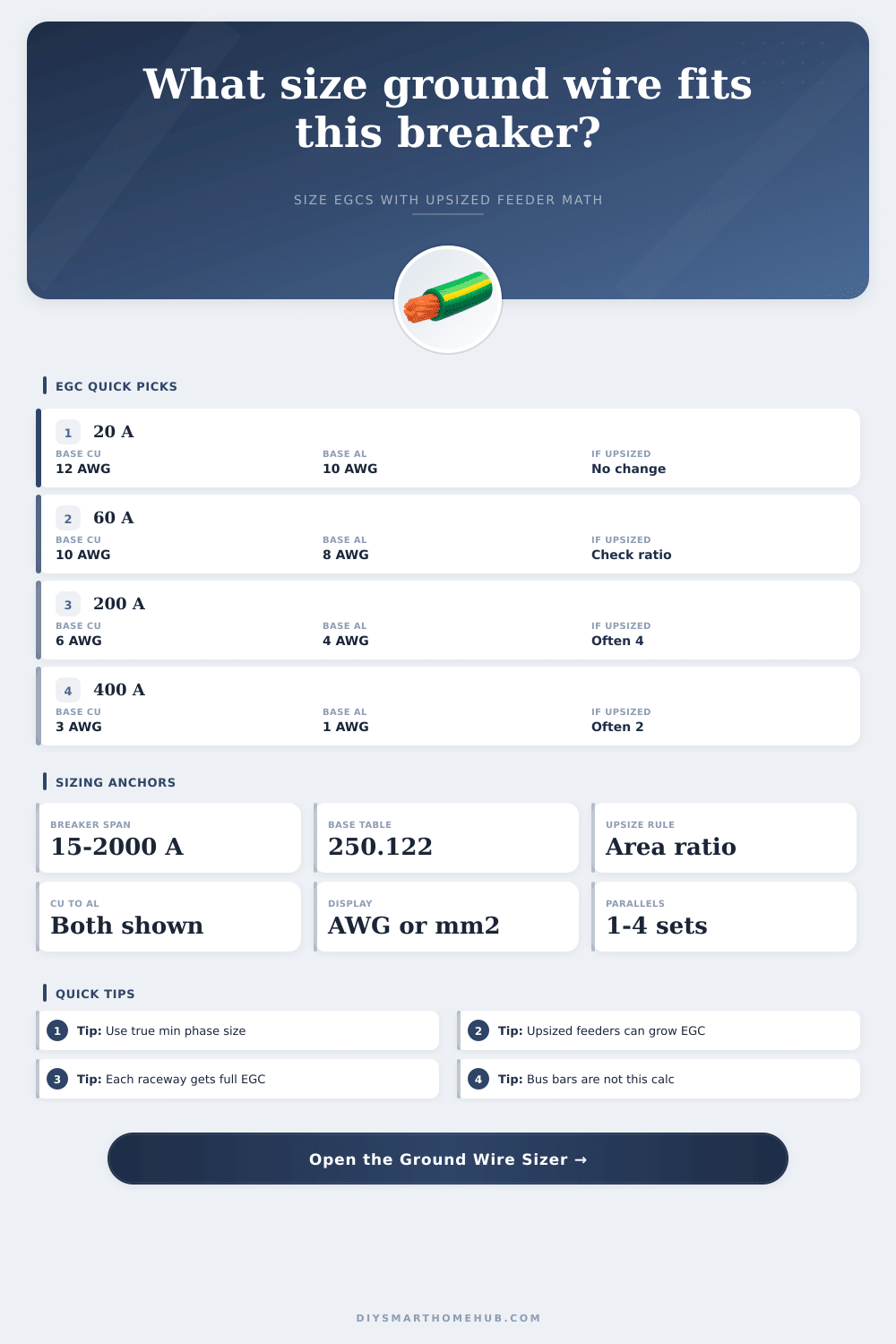
Calculate a wire-type equipment grounding conductor from breaker rating, then see whether the grounding conductor also has to grow when feeder or branch conductors were upsized beyond their minimum ampacity size.
📌Quick project presets
This tool is centered on equipment grounding conductors sized from the familiar breaker table and then increased by circular-mil ratio when the phase conductors grow beyond their minimum required size.
📏Calculation inputs
💡Live code cues
📊Ground wire results
⚙Code sizing anchors
📋Breaker-to-ground table
| OCPD not over | Copper EGC | Aluminum EGC | Copper area | Aluminum area |
|---|---|---|---|---|
| Sizing rows load here. | ||||
📐Conductor area map
| Size | Area | Metric eq | Typical use in this tool |
|---|---|---|---|
| Area rows load here. | |||
🗂Preset result snapshots
| Preset | OCPD | Phase ratio | Adjusted EGC | Per raceway |
|---|---|---|---|---|
| Preset rows load here. | ||||
The proportional rule depends on the conductor that would have satisfied ampacity before voluntary upsizing. If that baseline is wrong, the ground-wire result will drift too large or too small.
When the installation uses wire-type grounding conductors in multiple raceways, each raceway needs a full-sized grounding conductor matching the calculated result for that set.
An equipment grounding conductor is a wire that carries fault current back to the source. The equipment grounding conductor ensures that if an overcurrent device (like a circuit breaker or fuse) trip, that it does so with any fault in the circuit. If the equipment grounding conductor are too small, the breaker will not trip with the necessary speed to ensure safety.
The National Electrical Code (NEC) provide rules for the sizing of equipment grounding conductors in Table 250.122. Table 250.122 provides the relationship between the size of the equipment grounding conductor and the rating of the overcurrent device that protect the circuit. For instance, the NEC states that 20-amp circuits require equipment grounding conductors of 12 AWG copper, while 200-amp circuit require 6 AWG copper equipment grounding conductors.
How to Size Grounding Wires for Safety
Aluminum equipment grounding conductors must be two sizes larger than copper equipment grounding conductors in order to perform the same function of conducting fault current. Many electrical installation projects will require that the size of the phase conductors be increase beyond the requirements of the NEC. For example, the size of the phase conductors may be increased to account for voltage drop in the circuit due to an increase in the length of the circuit.
Additionally, the size of the phase conductors may be increased to account for future loads being added to those circuit. Finally, the size of the phase conductors may be increased to accommodate the terminal lugs that will be used to connect those conductors. When the size of the phase conductors is increased, the size of the equipment grounding conductor also must be increased according to NEC 250.122(B).
The size of the equipment grounding conductor is determined by dividing the area of the installed phase conductors by the area of the minimum required phase conductors, and multiplying that ratio by the base size of the equipment grounding conductor. The result of this calculation is rounded up to the next size of equipment grounding conductor according to standard wire sizes. The equipment grounding conductor must be sized according to the size of the phase conductors because the equipment grounding conductor is required to carry the fault current resulting from the faults in those phase conductors.
For example, if the minimum required size for phase conductors is 6 AWG copper, but conductors of 4 AWG are installed in order to reduce the voltage drop that occurs over the length of the circuit, then the area of the phase conductors has been increased. Therefore, the size of the equipment grounding conductor must also increase to ensure that the electrical system remain within its correct and safe operational parameters. Otherwise, the equipment grounding conductor will become a point of weakness in the electrical system.
The method for calculating the size of the equipment grounding conductor will differ according to the electrical configuration for the installation. For example, for configurations that use parallel raceway, the equipment grounding conductor must be installed in each of the raceways individually; the equipment grounding conductor cannot be split between more than one raceway. For instance, if an electrical installation requires raceways that can handle 400 amps of current and those raceways are split into two different conduit runs, each individual conduit will have to have its own equipment grounding conductor.
Additionally, the type of material that is used for the wires will impact the size of the equipment grounding conductor. Equipment grounding conductors that are made of copper will be smaller in size than those made of aluminum; however, aluminum is often used in electrical installations because it is less expensive than copper. Both copper and aluminum equipment grounding conductors will need to be calculate according to the rules established in the NEC tables.
There are some common error that can be made in the sizing of an equipment grounding conductor. For example, one error is to calculate the size of the equipment grounding conductor based off the base sizes established in the NEC tables without making adjustments according to the size of the phase conductors that are to be installed. Additionally, another error is to use the size of the installed phase conductors as the baseline for calculating the size of the equipment grounding conductor rather than using the minimum required size for the phase conductors according to the NEC tables.
If the installed size of the phase conductors is used as the baseline in this calculation, the ratio that is calculated will result in an incorrect size of the equipment grounding conductor that could potentially pose a safety risk to the installation. Furthermore, the equipment grounding conductor must be made of wire; using bus bars or structural steel in place of the equipment grounding conductor calculated according to the NEC tables will not meet the requirements for that electrical installation. Finally, the connections for all conductors must be secure.
All of the lugs that are used for the electrical installation will have to be torqued to the specifications that the manufacturer of those electrical components and materials states. The equipment grounding conductor lugs will also have to be torqued according to the specifications created for those types of equipment grounding conductors. Otherwise, the equipment grounding conductor may not effectively carry the fault current that may occur in the phases of that electrical installation.
By following these rules for the sizing and installation of the equipment grounding conductor, the equipment grounding conductor will be of the correct size for the phases of the installation, and the installation will meet the requirements established for electrical installations according to the NEC.