Geothermal Pipe Calculator
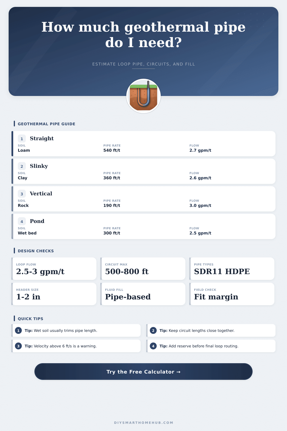
Estimate total loop footage, circuit count, fluid volume, and field footprint for horizontal straight, horizontal slinky, vertical U-bend, and pond coil geothermal layouts before detailed loop design.
⚙ Design Inputs
Start with a preset or enter your own loop assumptions. The calculator uses pipe-per-ton reference factors, design flow, circuit-length limits, and field spacing to plan a balanced geothermal loop.
📊 Pipe Sizing Results
📋 SDR11 Pipe Reference
These quick specs help match circuit pipe to loop flow, system volume, and typical geothermal loop use. Use the calculator above to estimate when you need more circuits instead of larger individual runs.
- Approx. inside diameter: 0.86 in
- Nominal fill: 2.5 gal per 100 ft
- Comfortable circuit flow: up to 6 gpm
- Best for short 1.5 to 2 ton circuit groups
- Approx. inside diameter: 1.08 in
- Nominal fill: 3.8 gal per 100 ft
- Comfortable circuit flow: up to 10 gpm
- Common residential horizontal loop choice
- Approx. inside diameter: 1.36 in
- Nominal fill: 6.2 gal per 100 ft
- Comfortable circuit flow: up to 16 gpm
- Useful for higher-flow manifolds and shared runs
- Approx. inside diameter: 1.76 in
- Nominal fill: 10.4 gal per 100 ft
- Comfortable circuit flow: up to 24 gpm
- Often used on large headers, pond loops, and duplex systems
🗺 Loop Footage Factors
Pipe-per-ton values below are planning numbers. Horizontal runs are expressed as total pipe, vertical values are bore footage before the calculator doubles them for U-bend pipe, and pond coils assume submerged loop density.
| Ground Condition | Straight Trench | Slinky Trench | Vertical Bore | Pond Coil |
|---|---|---|---|---|
| Dry sand or dry rock | 650 ft per ton | 520 ft per ton | 210 ft per ton | 360 ft per ton |
| Average loam | 540 ft per ton | 430 ft per ton | 190 ft per ton | 330 ft per ton |
| Moist clay | 460 ft per ton | 360 ft per ton | 170 ft per ton | 300 ft per ton |
| Wet soil or saturated bed | 400 ft per ton | 320 ft per ton | 150 ft per ton | 280 ft per ton |
| Total Loop Flow | Suggested Header | Typical Use | Velocity Goal |
|---|---|---|---|
| Up to 12 gpm | 1 in SDR11 | 2 to 4 ton residential | Below 5.5 ft/s |
| 12 to 20 gpm | 1-1/4 in SDR11 | 4 to 6 ton or multi-circuit fields | Below 5.5 ft/s |
| 20 to 32 gpm | 1-1/2 in SDR11 | Large homes, shops, duplex loops | Below 5.5 ft/s |
| More than 32 gpm | 2 in SDR11 | Commercial or shared manifold fields | Below 5.0 ft/s |
📈 Common Project Benchmarks
| Scenario | Load | Typical Pipe Plan | Circuits | Field Note |
|---|---|---|---|---|
| Small garage suite | 2 ton | 950 to 1,150 ft straight trench | 2 | Usually fits narrow backyard trenches |
| Average retrofit home | 3 ton | 1,600 to 1,900 ft straight trench | 3 | 1 in pipe stays balanced with 600 ft runs |
| Compact slinky yard | 4 ton | 1,550 to 1,950 ft slinky pipe | 3 to 4 | Higher packing reduces trench length |
| Tight urban vertical lot | 4 ton | 680 to 840 ft of bore, doubled for pipe | 3 to 4 bores | Bore spacing usually drives field fit |
| Large farmhouse or duplex | 5 to 6 ton | 2,400 to 3,200 ft total pipe | 4 to 6 | Header size often jumps to 1-1/2 in |
Try to keep parallel circuit lengths close together so purge flow, pump head, and loop temperatures stay predictable. Extra circuits often solve imbalance better than stretching one long run.
A loop can look correct on pipe-per-ton math and still fail the site. Compare trench, bore, or pond footprint early so your header route and spacing remain realistic.
Geothermal pipe calculator helps to guess how big must be the pipes for heat pump. Note that it gives only the smallest size. It is good idea choose the next bigger available option.
For sizing earth loop, match it to the home and to the heat pump, with that it is tied. The first step in that process is have right calculation of heat loss and heat gain according to Manual J.
How to Choose the Right Pipe Size for a Geothermal Heat Pump
Certain tools as Geo-Flo Calculators guess close drop in earth loops and help size the pump. Also other design and service tools exist. The calculator of PPI for plastic pipe design bids five main functions.
They deal about pressure and head loss, pipe mass and volume, thermal expansion and shrinking, hydraulic shock and expansion arm or loop. In addition, it counts pressure of still water column. That programming answers for uses as hydronic piping, radiant heating and cooling, snow and ice melt and geothermal earth loops.
You use it also for plumbing, water service, fire protection, local heating and turf prep.
Picking the right pipe diameter is key in the whole process. For connections of geothermal collectors you commonly choose diameters 20, 25, 32, 40, 50, 63, 75, 90, 110, 125, 140, 160 or 180. Simple rule says 150 feet of borehole for one ton of capacity.
But it does not think about important things as pipe diameter. For instance, difference between 1.25 inch and other sizes matter. Other way think that: for 1 ton of geo pipe loop you need around 1300 square feet of home.
For nice cabin can be necessarily more, because such houses usually poorly insulate.
Different pipe materials have different values of thermal conductivity. Copper pipe reaches 13.11 W/m²K, during PE pipe only 7.09 W/m²K. Long pipe pieces equalize the temperature.
For instance, water enters in 40 degrees and exist in 50 degrees. For lessen temperature swings, loops recline in around 20 feet of depth. You can also use a free thermal expansion calculator to guess linear extension in pipe systems by material and lowest or highest temperatures.
That covers pipe size, depth, flow and pressure drop.