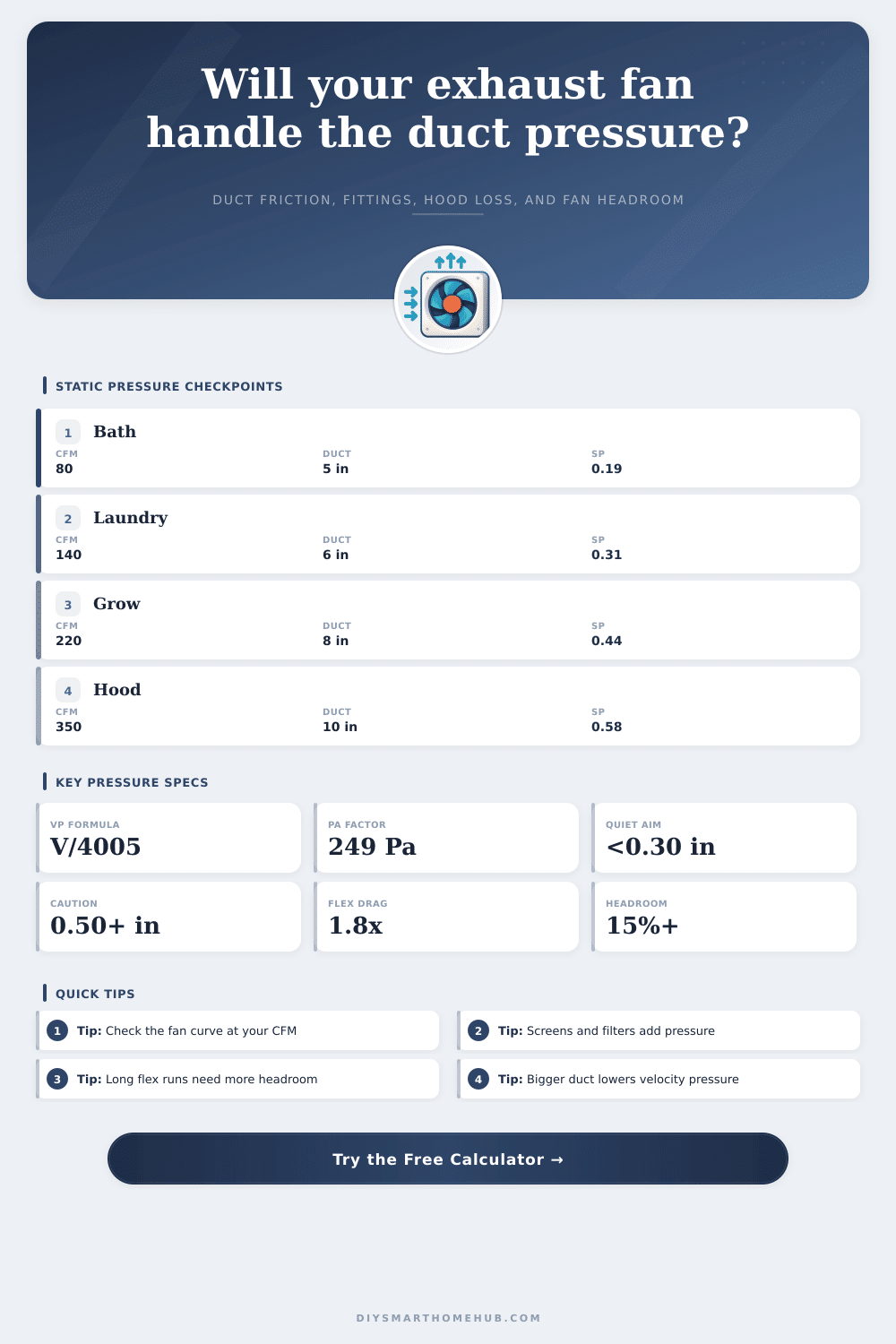
Exhaust Fan Static Pressure Calculator
Estimate total static pressure for a bathroom fan, laundry exhaust, grow tent, utility vent, or light hood by combining duct friction, velocity pressure, fittings, filters, hoods, dampers, and fan-curve headroom.
📌Duct system presets
🔧Static-pressure inputs
Static pressure result
Enter airflow, duct, fittings, filters, and fan curve details to estimate total external static pressure.
🧪Selected fitting and filter spec grid
📐Pressure range table
| Total static pressure | Pa equivalent | Typical meaning | Fan curve action |
|---|---|---|---|
| Under 0.20 in w.g. | Under 50 Pa | Short, open residential duct path | Most listed bath fans can hold rated flow |
| 0.20 to 0.35 in w.g. | 50 to 87 Pa | Normal elbows, cap, and modest filter loss | Check curve but headroom is often workable |
| 0.35 to 0.55 in w.g. | 87 to 137 Pa | Long duct, flex, roof cap, or loaded screen | Use high-static or inline fan curve data |
| 0.55 to 0.80 in w.g. | 137 to 199 Pa | Restrictive hood, carbon filter, or undersized duct | Upsize duct, reduce fittings, or choose stronger fan |
| Above 0.80 in w.g. | Above 199 Pa | Special exhaust path or severe restriction | Fan selection should be based on a full curve |
🔁Fitting equivalent length table
| Fitting | Default rule | Pressure effect | Calculator treatment |
|---|---|---|---|
| 90-degree elbow | 15 to 32 duct diameters | Higher with flex or tight radius | Added to equivalent length per elbow |
| 45-degree elbow | 8 to 16 duct diameters | About half a full elbow | Added to equivalent length per elbow |
| Wye, tee, or transition | 12 to 24 duct diameters | Depends on branch angle and reducer shape | Added to equivalent length per fitting |
| Wall hood damper | 20 duct diameters plus loss | Damper blade and outlet hood add resistance | Equivalent length plus hood static loss |
| Roof cap with screen | 35 duct diameters plus loss | Screen and weather hood can dominate small fans | Equivalent length plus hood static loss |
🌬Filter and hood loss table
| Restriction | Base drop | Base airflow | Best use |
|---|---|---|---|
| Decorative grille or mesh | 0.03 in w.g. | 80 CFM | Small bath or powder room exhaust inlet |
| Laundry lint screen | 0.08 in w.g. | 120 CFM | Laundry and utility exhaust paths |
| MERV 8 prefilter | 0.12 in w.g. | 200 CFM | Dust control before inline fan |
| MERV 13 compact filter | 0.28 in w.g. | 200 CFM | Higher capture with larger fan reserve |
| Carbon canister filter | 0.45 in w.g. | 250 CFM | Grow tent or odor-control exhaust |
| Range hood grease filter | 0.18 in w.g. | 300 CFM | Light cooking exhaust path check |
📋Common exhaust system examples
| System | Airflow | Duct and run | Pressure planning note |
|---|---|---|---|
| Short bath fan | 80 CFM | 5 in, 12 ft | Usually under 0.25 in w.g. with a clean wall hood |
| Long attic bath | 100 CFM | 6 in, 42 ft | Roof cap and flex sag often decide the fan curve |
| Grow tent carbon | 220 CFM | 8 in, 18 ft | Carbon filter can be larger than duct friction |
| Light range hood | 350 CFM | 10 in, 20 ft | Grease filter plus hood outlet needs curve margin |
💡Static pressure tips
In the master bathroom, a quiet exhaust fan that is installed doesn’t move much air and make all kinds of noise. The motor isn’t typically the culprit here. Instead, it’s static pressure resisting flow. Imagine holding your nose closed while trying to blow through a long thin straw. That’s static pressure in action.
While the calculator above do the math for you, knowing what’s creating this resistance will help you avoid purchasing the incorrect equipment. Static pressure isn’t one thing. It’s a collection of little things. Air rubbing against walls causes friction. An elbow or grille disrupt the air flow. This causes turbulence, which cause chaos. Caps and filters is roadblocks that keep pests and smells out. They each cause resistance. Take long flex ducting and add in sharp elbows and a restrictive filter and the penalties accumulate fast. On paper it looks great; in reality it fail.
Why Your Exhaust Fan Is Quiet and Noisy
And the inputs? They are real-world tradeoffs. Specifically, the duct diameter: doubling the duct size drastically reduces velocity, which in turn reduce friction loss considerably. Even when two pieces of duct carry an equal amount of air, a six inch duct will move it more easiler than a four inch tube.
Also the material of the duct makes a difference. Metal (or smooth plastic like PVC) allow air to move through with less drag different than flexible material such as foil ducting. Internal ribs in foil ducting cause turbulence and require more pressure to push air. While that may seem small, it accumulate over longer distances.
Then there are filters: while a MERV 13 will block more smells and particulate from entering your space, it create more pressure to push air. This cost can’t be ignored. Don’t calculate for friction loss in your ducts and forget about the filter. You’ll end up with an overly optimistic estimate.
These are true airflows. So the calculator takes into account resistance at those values. Why does that help? Resistance isn’t linear. Typically, if you double the air being pushed through the duct, you need four times the pressure to do it. It’s a quadratic relationship which catch a lot of people off guard. This is where theory meets reality on fan curves.
Most fans is rated for free air flow. What does that mean? When there is no resistance behind the fan, it moves its maximum CFM. It’s a lab-only scenario. In the real world, there is always some amount of resistance from your ductwork. Your goal is to understand the pressure that a particular fan can produce at any desired CFM. If the total static pressure required by your entire system are greater than what the fan can achieve, then your actual CFM will decrease. And often times it decreases significanly.
Building headroom into each design serve as a safety buffer. Creating a 15-20% reserve protects against lower CFM performance when dampers become stiff or filters clog with dust. Without this margin, even a well-designed system could of fail after a year.
The tool allows for visualizing the difference between what the fan can deliver vs. What the ductwork require. For some perspective, the average range of pressures can be found on the page’s reference table. A simple home system will be at the lower end while complicated ones like long runs through an attic or carbon filtration systems gets higher. This allows you to determine if using a regular inline fan would work based off your project. Or if you should scrap everything and look at changing ducts.
Remember, the ideal number isn’t what we are striving for here. We are just trying to find out if there is any airflow at all. To begin, measure the longest run length. Count up all elbows. Find the most restrictive filter. And input that information into the calculator. That math will show if your plan will work as-is or needs simplification. Most times it is simply switching over to larger ducting or eliminating an additional bend that cause the issue. And it is never too costly, but it matters once you turn the system on.