Ethernet Cable Loss Calculator
Estimate insertion loss, PoE voltage drop, copper heat, and practical channel reach for cameras, touch panels, wireless access points, and rack uplinks before you commit to a cable category.
1 Quick Presets
2 Link Inputs
Run length is one-way from switch or injector to the device. The tool adds connector loss on top of cable attenuation and estimates PoE voltage using the selected pair mode, cable loop resistance, and ambient temperature.
Loss Breakdown
3 Selected Cable Specs
4 Reference Tables
Application Frequency Guide
These profiles approximate where each link type places most of its insertion-loss stress and how much total channel loss is still considered comfortable after adding design margin.
| Profile | Reference freq | Budget | Typical use |
|---|---|---|---|
| Fast Ethernet control | 31.25 MHz | 13.0 dB | Controllers, hubs, touch gateways |
| Gigabit LAN or camera | 62.5 MHz | 18.8 dB | NVR cameras, media streamers, switches |
| 2.5G Wi-Fi 6 AP | 100 MHz | 24.0 dB | Ceiling APs and stronger edge uplinks |
| 5G Wi-Fi 7 or bridge | 200 MHz | 29.0 dB | Shorter high-throughput backhaul links |
| 10G NAS or backbone | 400 MHz | 39.5 dB | Server rack, storage, or switch uplink |
Cable Category Comparison
Loop resistance and high-frequency attenuation both matter in a smart home. Lower resistance helps PoE delivery, while lower attenuation keeps multi-gigabit and 10G channels inside their loss budget.
| Category | Bandwidth | Loop ohms / 100 m | 10G reach | Best fit |
|---|---|---|---|---|
| Cat5e UTP | 100 MHz | 18.8 | 35 m practical | Doorbells, cameras, control links |
| Cat6 UTP | 250 MHz | 14.8 | 55 m practical | APs, media points, moderate PoE |
| Cat6 CMP | 250 MHz | 14.3 | 55 m practical | Plenum spaces with similar data performance |
| Cat6A F/UTP | 500 MHz | 13.6 | 100 m standard | Longer multi-gig and 10G runs |
| Cat7 S/FTP | 600 MHz | 13.2 | 100 m standard | Noisy spaces, shielded equipment rooms |
| Cat8 S/FTP | 2000 MHz | 12.8 | 100 m standard | Very short dense rack links |
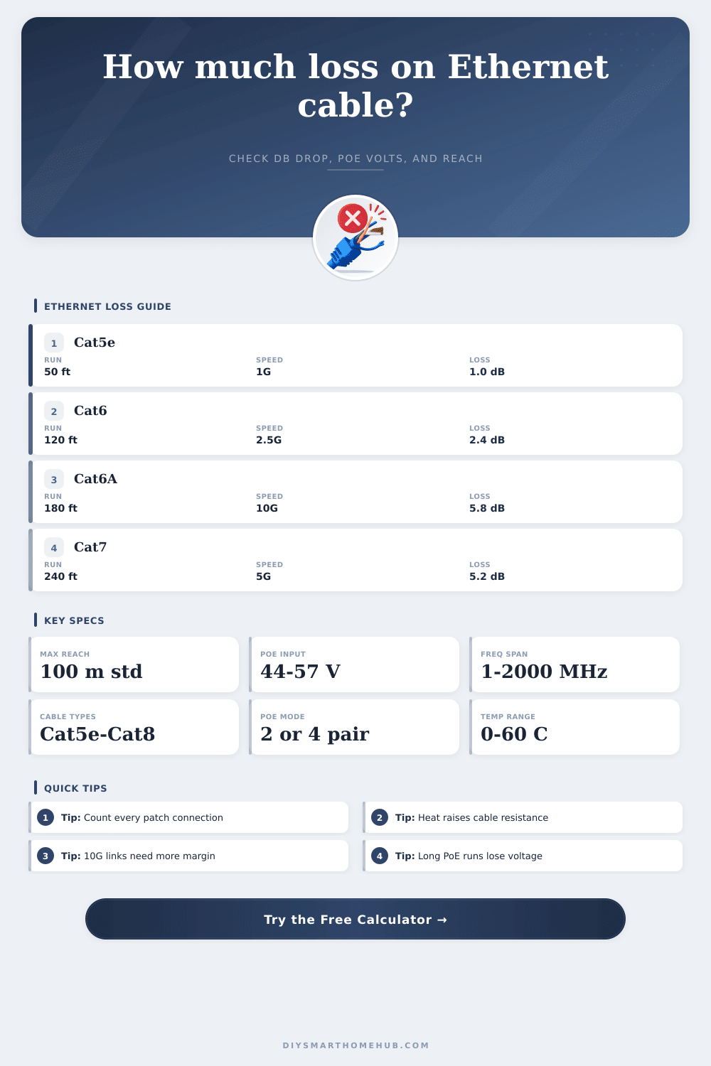
Common Smart-Home Scenarios
These examples assume structured terminations, moderate ambient temperature, and 10 percent design headroom so you can sanity-check your result against everyday residential links.
| Scenario | Run | App | Est. loss | Suggested cable |
|---|---|---|---|---|
| Video doorbell | 50 ft | 1G | About 1.0 dB | Cat5e or better |
| Ceiling AP | 120 ft | 2.5G | About 2.4 dB | Cat6 or better |
| Detached garage switch | 280 ft | 1G | About 6.1 dB | Cat6A for PoE margin |
| Rack uplink | 90 ft | 10G | About 3.1 dB | Cat6A or Cat7 |
| Backyard bridge | 220 ft | 5G | About 8.4 dB | Cat6A shielded |
Connector count matters more as frequency climbs. A 10G or 5G link that looks fine on cable-only attenuation can still run short on total channel margin once patch panels, couplers, and field plugs are added.
For smart home cameras and access points, lower resistance can matter as much as lower insertion loss. A run may pass the data budget while still dropping too much voltage for a warm high-wattage PoE device.
EtherChannel signal losses and PoE voltage drops are two factors to understand as they may lead to devices malfunctioning. Should a technician install a device that utilizes ethernet cables for both data and power, such as a video doorbell or security camera, the signal loss or voltage drop could lead to stuttering video or devices that continuously reboot. Signal loss, also known as insertion loss, occur with ethernet cables due to the frequency of the signal.
The higher the frequency of the signal, the more signal loss that will occur along the length of the ethernet cable. For instance, data speeds of 2.5G and 10G requires higher frequencies in the signal than the standard gigabit ethernet speeds. Higher frequencies lead to attenuation along the copper ethernet cable due to the resistance in that cable converting some of the data to heat.
Why Ethernet Cables Lose Signal and Power
Consequently, the higher the frequency of the data signal and the longer the length of the ethernet cable, the more signal loss will occur. Another of the main factors that can contribute to signal loss along an ethernet cable is temperature. As the temperature of the ethernet cable increases, the resistance in the copper components of the cable increase.
For every degree that the resistance increases, the resistance of the copper in the ethernet cable increases by approximately 0.4%. Should the ethernet cable be running through an attic, for instance, the heat within the attic will increase the resistance of the copper in that ethernet cable. Increased resistance will lead to increased signal loss and decreased PoE voltage levels along that cable.
Thus, a cable that can support the data requirements of a device in a cool environment may not have enough power to operate that device if it is located in a warm environment. Connectors also contribute to signal loss along an ethernet cable. Each time an ethernet cable passes through an RJ45 connector, patch panel, or coupler, signal loss is introduced into the system.
Factory made keystone jacks tend to have less signal loss than couplers, and shielded connections can help to reduce the amount of noise introduced into the system at high frequencies. Each connection along an ethernet cable reduces the amount of signal that can travel along the cable. Power over Ethernet introduces additional complexity into ethernet cabling systems.
PoE voltages and currents travel along the ethernet cable. Voltage drops along an ethernet cable in relation to the resistance of the cable and the amount of current traveling along that cable (Ohm’s law). If a system utilizes two-pair PoE mode, there is less of the cable utilized than if the user uses four-pair PoE++ mode.
Additionally, current create heat along the ethernet cable. This heat increases the resistance of the copper along the cable, leading to more voltage drops along the cable. Thus, heat and resistance are directly related to one another leading to the formation of a feedback loop.
Finally, the installation of an ethernet cable can also affect the signal and the heat create by the cable. Should many ethernet cables be bundled together in the same conduit, more heat will be created along those cables than if each ethernet cable was installed individually in the air. The heat created by one ethernet cable will impact the temperature of the other ethernet cables in the same bundle.
Thus, you must account for heat created by the ethernet cables in the planning of the installation. The length of an ethernet cable can be determined based off the factor that presents the most challenge for the installation. It is possible that the length of the cable may be sufficient to allow the data signal to travel along the cable, but it may be too long to allow the PoE voltage to reach the device.
Therefore, you must evaluate both data and PoE requirements for the device to determine the maximum distance that the ethernet cable should be installed. For instance, a 10G connection requires more headroom in the ethernet cable than a gigabit connection, and more Cat6A cable is required. If ten percent headroom is allowed for the installation, that ten percent can be used to provide for potential increases in resistance caused by heat or the number of connections along the ethernet cable.
When installing an ethernet cable, ensure that each connection is accounted for along the cable, ensure that the temperature of the environment is considered, account for any bundling of the ethernet cabling, and ensure that the maximum length of the ethernet cable is determined according to the most restrictive requirement. In addition, not all Cat6 ethernet cables are created equal. Additionally, the bandwidth requirements of many devices, such as access points, are high.
Using keystone jacks is generally better than using field plugs. Finally, an ethernet calculator can assist in determining the total length of the ethernet run by accounting for type of cable, temperature, and bundling of the ethernet cables. To be honest, you should of checked the cables first to ensure they are actualy moddern.
Its important to recieve the right components so you dont have issues later. There are alot of ways to avoid these problems, and you’ll want to make sure yours are set up correctly.