Earth Fault Current Calculator
Estimate phase voltage, earth loop impedance, neutral grounding resistance effect, soil and electrode contribution, available earth fault current, touch voltage, and breaker or RCD trip margin.
Earthing System Presets
Choose a starting point for the earthing arrangement, protection device, source, feeder, and soil path, then adjust the measured values for the actual circuit.
Fault Loop Inputs
Earth Fault Results
Calculation Breakdown
Earthing and Protection Spec Grid
Earthing System Reference
| System | Main return path | Calculator emphasis | Protection note |
|---|---|---|---|
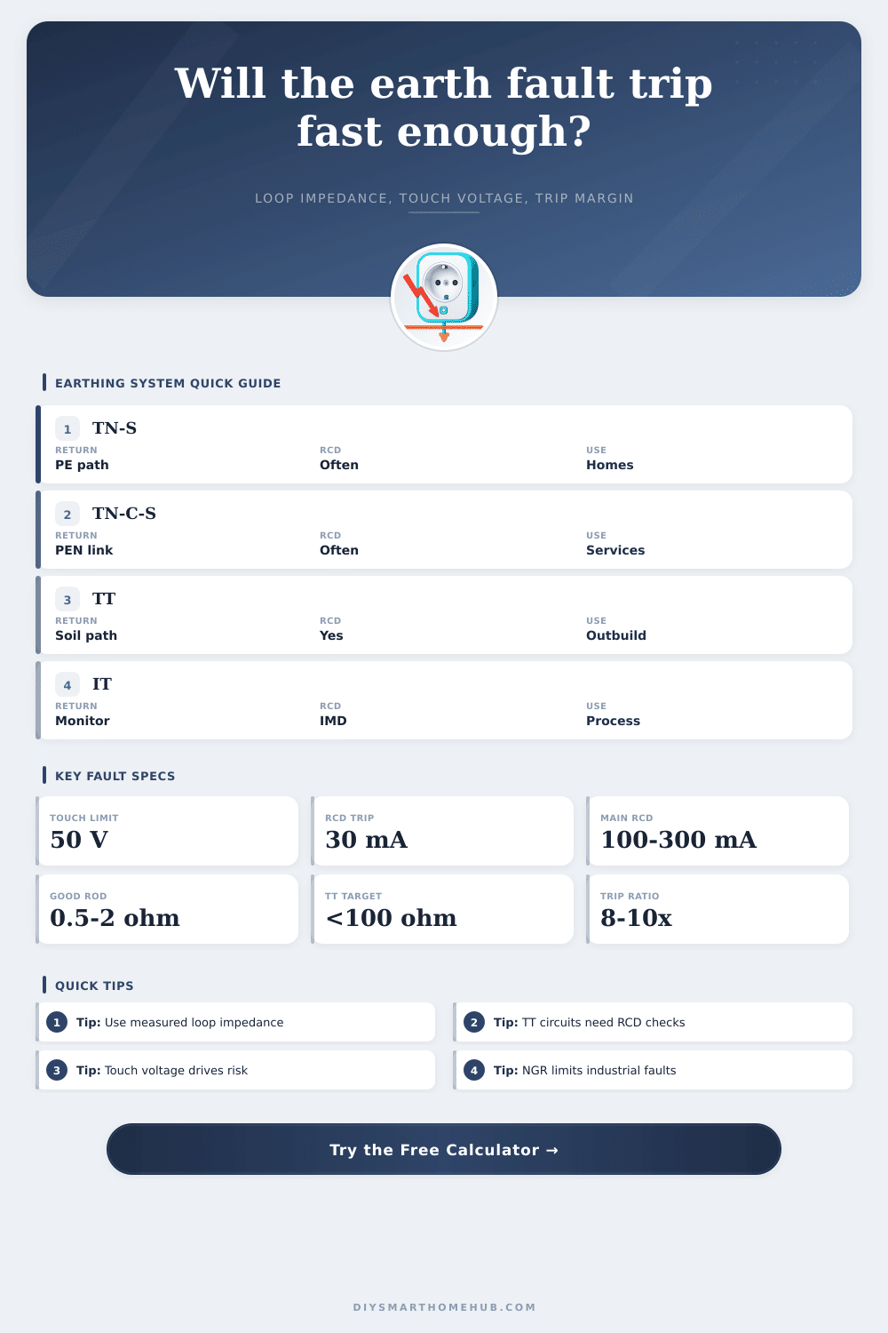
| TN-S | Separate PE conductor | Source plus conductor loop | Breaker trip often possible if Zs is low |
| TN-C-S / PME | Combined PEN before service | Very low service return impedance | Check bonding and PEN assumptions |
| TT | Electrode and soil path | Soil and rod resistance dominate | RCD margin is normally the key check |
| Resistance grounded | Neutral grounding resistor | NGR intentionally limits current | Device setting must match limited current |
| High-resistance grounded | High-value neutral resistor | Fault current can be only a few amps | Alarm and locate first fault |
| IT isolated | Insulation and monitor path | First fault is restricted by isolation | Second fault needs separate study |
Protection Threshold Table
| Device | Trip basis | Calculator threshold | Best-fit use |
|---|---|---|---|
| Type B MCB | 3 to 5 times rating | 5 x breaker amps | General circuits with low inrush |
| Type C MCB | 5 to 10 times rating | 10 x breaker amps | Moderate motor or transformer inrush |
| Type D breaker | 10 to 20 times rating | 20 x breaker amps | High inrush industrial loads |
| MCCB instantaneous | Adjustable magnetic pickup | 10 x selected amp rating | Panel feeders and distribution |
| RCD / GFCI | Residual current setting | mA rating converted to amps | TT, outdoor, and personal protection |
| IMD alarm | Insulation monitor setting | Alarm threshold only | IT systems with first-fault continuity |
Soil and Electrode Contribution Table
| Electrode condition | Typical resistance | Soil factor | Modeling note |
|---|---|---|---|
| Ground ring or grid | 0.5-2 ohm | 0.7-1.0 | Strong contribution in TN and TT models |
| Multiple bonded rods | 2-25 ohm | 0.7-1.6 | Parallel rods lower effective resistance |
| Single rod in average soil | 10-50 ohm | 1.0 | Common TT planning starting point |
| Dry sand or gravel | 50-200 ohm | 1.6 | RCD trip margin becomes critical |
| Rocky or frozen soil | 100+ ohm | 2.4 | Use measured resistance before relying on model |
Common Circuit Benchmarks
| Circuit | Earthing profile | Expected result | Secondary check |
|---|---|---|---|
| Home final circuit | TN-S or TN-C-S | High enough current for MCB | Measured Zs at far outlet |
| Detached outbuilding | TT electrode | Breaker current often too low | 30 mA or 100 mA RCD margin |
| 480 V MCC | Solid or resistance grounded | NGR can cap fault current | Ground relay pickup |
| Data room HRG | High-resistance grounded | Low current, alarm-focused | Insulation monitor response |
| Generator feeder | Separately derived TN | Source impedance can be higher | Generator fault decrement |
| EV outdoor circuit | TN or TT with RCD | Touch voltage drives review | RCD setting and electrode value |
Earth Fault Calculation Tips
High pressure hoses have hidden leaks, just like earth faults. Until that stray current meets a human finger tip, the system keeps running, and by then it’s too late. Earth fault current isn’t academic. It can mean the difference between a breaker tripping within seconds to save lives or a circuit staying red-hot long enough to start a fire.
Because we can easily measure voltage drop or thermal ratings, most electrician spends their time on these numbers. But fault paths? They’re hidden until they’re needed. Use this tool to build the hidden resistance of your installation before pulling a single wire.
How to Calculate Electrical Safety Correctly
The basic premise centers on loop impedance, or how much resistance the current experiences as it exits its path and attempts to find its way back to source. There’s the phase conductor heading outward, the point of fault itself, then the return path where all this electricity goeses back. That return path in most moddern homes using a TN system is typically a separate protective earth wire traveling parallel to your hot conductor. It’s simple math: Low loop impedance results in high-current spike and blown breaker.
But then we’re into older houses/builder, rural areas, etc., and it gets interesting. In either case, the choice of earthing system is most important. Are you using a TT system, like a detached shed with a ground rod of its own? The current returns through the dirt instead of copper. Grounding electrode resistance varies with soil’s temperature, makeup, and moisture content. A cold winter or dry summer can double your grounding electrode resistance overnight.
This is accounted for in the calculator, which allows changing configuration of electrodes and soil resistivity factors. No need to become a geologist here, just know that clay soil does better than sandy soil. Setting realistic expectations will help: if your results seem too good to be true, they likely are.
Another vital parameter to watch out for is touch voltage. This measures how much potential there is between any live parts in the event of a fault and the ground beneath our feet. High touch voltage may kill even when a breaker doesn’t trip instantly. Typically touch voltage is limited by standards to not more than fifty volts in general areas which makes it safe for humans. So if your calculation shows touch voltage beyond this then you have an issue regardless of blown fuses. Perhaps it is time to upgrade your earthing scheme or install residual current devices that will trip the circuit before the overcurrent protection.
To select the proper protection device and know when it is tripped, you must also understand the concept of trip margin. With magnetic breakers this means knowing that they are designed to snap open with high currents. Because long cable runs can reduce fault current and smaller wire gauges does as well, if the fault current is insufficient then your breaker won’t see any surge and just continue carrying the fault current until some insulation melts. This is common on long branch circuits running out to remote loads. Comparing your chosen device’s trip threshold to your available fault current helps the calculator find those weak spots.
For example, a thirty milliamp residual current device trips at very little leakage making it perfect for high impedance situations where overcurrent devices fails to protect. The quality of connections also tends to be undervalued. A loose splice or corrosion on a terminal block will increase resistance and you’ll never see it on a schematic. Perfect numbers on paper don’t mean squat if your workmanship isn’t up to par. Always compare your numbers to what you measure in the field. Set your design goals using the tool and then check your installed circuit to make sure what’s out there matches theory. If not, you’ve got a problem somewhere, maybe degraded conductors or even a broken neutral link.
So grounding isn’t just some law that you follow to stay out of jail, it’s also how you ensure that the system will respond correctly and consistently when something goes wrong. You don’t want some unclear outcome because you gave it an unclear path. The presets on the calculator give you a starting point for typical setups such as an industrial panel or residential feeder. From there adjust the parameters to fit what was installed at your site. Adding parallel return paths can be the difference between a hazard and a trip. Adjusting the conductor size makes all the differance too.
So basically you’re creating a safety net here. Under normal conditions, the power flows through the wires. When something goes wrong, it flows through the earth path. Ideally, you would of want a backup system strong enough to trip protection as soon as possible. It should be subtle enough that it doesn’t interfere with everyday operations. Respect the soil conditions if using electrodes, get the loop impedance correct, and always test for yourself in the real world. Having a circuit that appears perfect on paper but fails in practice is actualy worse than having no plan at all. Make sure your return paths are low resistance, clean and short. This will keep the current where it should be.