Copper Busbar Resistance Calculator
Estimate copper busbar cross-section, temperature-corrected resistance, voltage drop, I2R heat, and current density for short DC or AC distribution links.
⚙Busbar presets
📏Busbar dimensions and load
Calculated busbar result
Results update from the selected copper alloy, geometry, temperature, and joint allowance.
🔬Selected copper spec grid
📊Common busbar size snapshots
| Nominal copper bar | Area | Resistance at 50°C, 1 ft | Current density at 200 A |
|---|---|---|---|
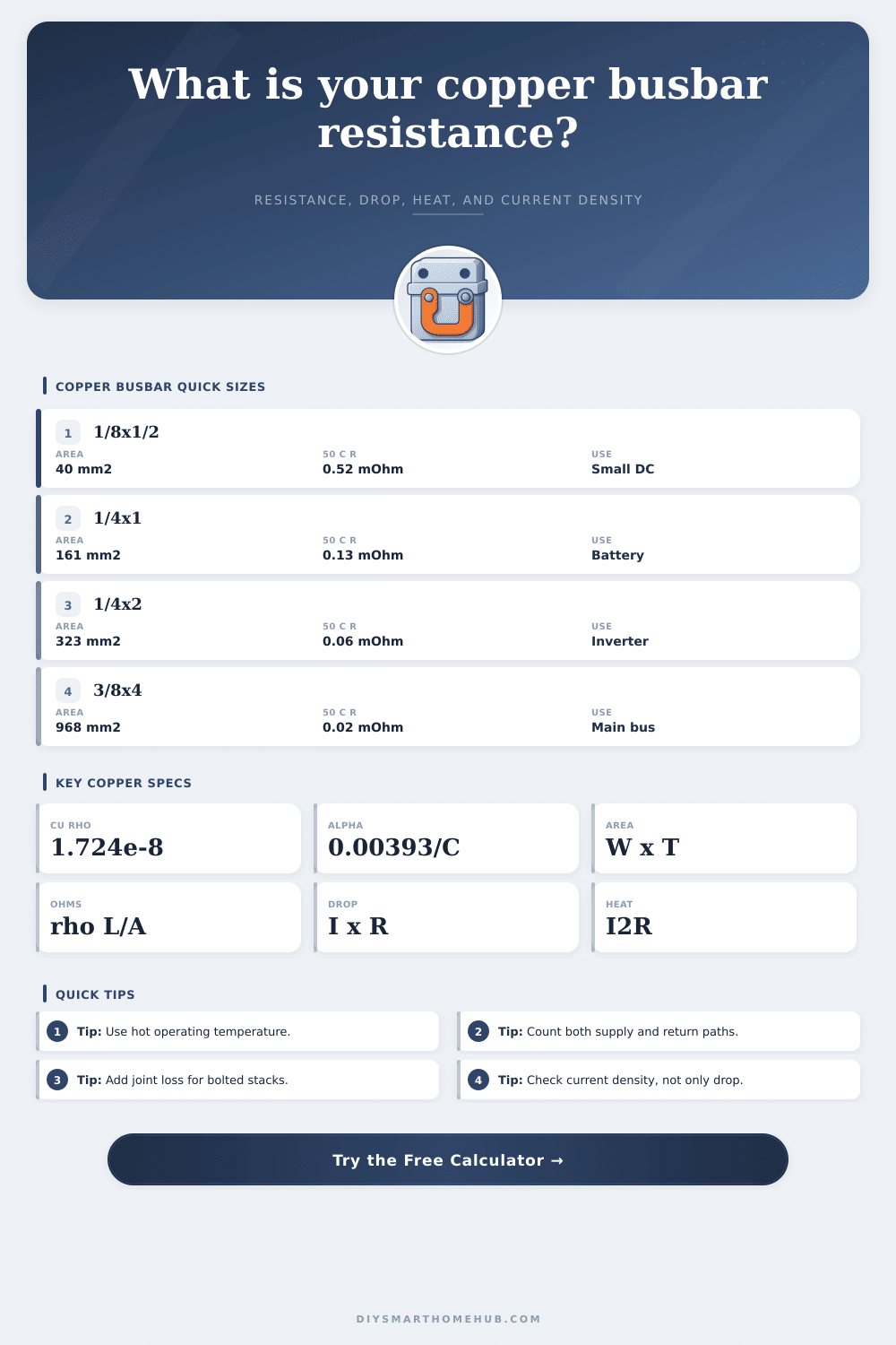
| 1/8 in x 1/2 in | 40.3 mm² | 0.524 mΩ | 4.96 A/mm² |
| 1/8 in x 1 in | 80.6 mm² | 0.262 mΩ | 2.48 A/mm² |
| 1/4 in x 1 in | 161 mm² | 0.131 mΩ | 1.24 A/mm² |
| 1/4 in x 2 in | 323 mm² | 0.065 mΩ | 0.62 A/mm² |
| 3/8 in x 4 in | 968 mm² | 0.022 mΩ | 0.21 A/mm² |
🧪Copper alloy and conductivity grid
| Alloy | Typical conductivity | Resistivity at 20°C | Use in calculator |
|---|---|---|---|
| C101 oxygen-free copper | 101% IACS | 1.707e-8 Ωm | High conductivity reference bus |
| C110 electrolytic tough pitch | 100% IACS | 1.724e-8 Ωm | Common busbar baseline |
| C145 tellurium copper | 93% IACS | 1.854e-8 Ωm | Machinable copper parts |
| C260 cartridge brass | 28% IACS | 6.157e-8 Ωm | Compare brass hardware loss |
| C172 beryllium copper | 22% IACS | 7.836e-8 Ωm | Spring contact comparison |
🌡Temperature and current density reference
| Check item | Typical planning band | Calculator field | What it changes |
|---|---|---|---|
| Cool enclosed bus | 30°C to 45°C copper | Expected copper temperature | Small resistance increase over 20°C |
| Warm cabinet bus | 50°C to 70°C copper | Expected copper temperature | Often 12% to 20% higher resistance |
| Low current density | Below 1 A/mm² | Width, thickness, parallel bars | Lower voltage drop and heat |
| Moderate current density | 1 to 2 A/mm² | Width, thickness, parallel bars | Needs enclosure temperature review |
| High current density | Above 2 A/mm² | Width, thickness, parallel bars | Requires detailed thermal design |
📐Formula table
| Formula | Expression | Units | Result role |
|---|---|---|---|
| Cross-section area | A = width x thickness x parallel bars | mm² | Sets conductor area |
| Temperature correction | ρT = ρ20 x (1 + alpha x (T - 20)) | Ωm | Raises resistance when hot |
| Conductor resistance | R = ρT x length / area | Ω | Calculates busbar mΩ |
| Voltage drop | Vdrop = current x resistance | V | Compares to system voltage |
| Power loss | P = current² x resistance | W | Shows I2R heat to dissipate |
💡Calculation tips
Electrical failures aren’t usually caused by insufficiently sized wiring for continuous loads. Rather, it’s because somewhere along the way, somebody forgot about how heat build up when current meets resistance in a warm, closed space.
Large gauge copper bus bars can move large amounts of electricity around without much fuss. If you size them properly, they’ll move huge amounts of electricity while losing very little themselves. How do you know? Well, knowing your geometry is just one part of the equation. You also has to consider things like temperature rise, the imperfection of your joints, and the real-world route of electrons from source to load.
Why Busbars Get Hot and How to Fix It
The calculator on top does all of this work for you so you don’t have to mess with all those units yourself. Let’s begin with the physical cross-section. The cross section of a busbar is not a round wire, so it will depend on both thickness times width. And why does that matter? Because the resistance is inversely proportional to that cross-sectional area. So if your cross-sectional area doubles (by making it twice as thick), the resistance are cut in half (assuming the same length).
But wait, what about length? Length can be confusing here. The problem is that DC systems needs current to return back to source. That means if you take a single bar out to a load and then send current back on another path, that’s actualy double the physical length of the resistive path. That means we don’t want to underestimate our voltage drop based off length. We’re only accounting for the actual length once, not twice. To compensate for this, the tool has a path multiplier setting that multiplies effective length before calculating resistance. It’s a little setting but makes a big difference in result.
Where many designs fall apart in the field is when it comes to temperature. As copper heats up, its resistivity also rises. Copper have a typical base-line resistivity at twenty degrees Celsius. However, that busbar can be sitting in an electrical cabinet. The cabinet may be full of contactors and inverters running hard. It’s easy to hit temperatures of fifty or sixty degrees Celsius. At these warmer temps, the resistance rise almost fifteen percent over room temperature. You’ll do a calculation based off its cold resistance value, which makes your voltage drop look OK on paper. But what it does is drag down the performance of your system. The temperature coefficient of copper is used here to correct for that so that your results reflect how the system performs when hot, instead of showing values measured while it was cool first thing in the morning.
Another sneaky place you lose it: Joints. Bolted joints adds some level of contact resistance, even if your copper’s joint surface is perfect. A little gap or different pressures on two surfaces adds a few milliohms that don’t appear in the bar itself but will still accumulate on long runs. Enter the number of joints at an interface and the estimated contribution of each one. For high-current applications where every milliamp counts, even a small amount of additional resistance becomes a real heat producer. This increases the local temperature which causes more heating. This creates a positive feedback loop that can weakens connections and damage insulation over time if allowed to run.
Current density is key here. If you keep it low (amperes per square millimeter), then you ensures that the busbar remains sufficiently cool to be structurally and electrically sound. The other factor is alloy choice. For most buswork, the default alloy is C110 electrolytic tough pitch copper. There are other alloys that provide additional strength (beryllium copper) or machinability (tellurium copper) at the expense of conductivity. That shows up on the page’s reference table where different materials’ effect on resistivity is laid out. You can see how much the difference is when you compare solid copper bars vs brass hardware. It may be machinable, but that costs you both heat generation as well as increased voltage drop. Knowing that trade-off lets you make a smart decision about what material is right for each use. That keeps you from spending unnecessarilly for excess conductivity.
So bottom line on busbars is they are designed for both current and heat. Sometimes a bar that looks too large for its voltage drop may actualy be undersized because heat gets trapped in a poorly ventilated box. That’s where the electrical aspect comes into play with the tools. Now you must ask whether the physical world can support the thermal load of your design. Want a system running cool at max load? You don’t want one running just below failing until next inspection. You could of avoided expensive retrofitting later by getting the resistance right from the start. Keep the power where it belongs; in the circuit, not in the insulation.