CCTV Camera Power Consumption Calculator
Estimate camera watts, daily and monthly energy, PoE budget headroom, and UPS runtime for wired, WiFi, PoE, infrared, and PTZ surveillance layouts.
Calculation Breakdown
| Camera type | Typical watts | Peak watts | Best use in calculator |
|---|---|---|---|
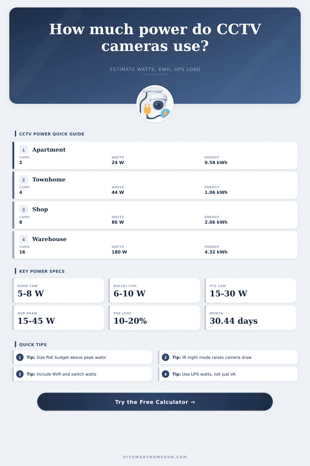
| Mini indoor WiFi camera | 2.5 to 4 W | 5 W | Rooms, nursery, apartment interior |
| Fixed PoE dome | 5 to 7 W | 9 W | Ceiling cameras with moderate IR |
| IR bullet PoE camera | 6 to 10 W | 13 W | Driveway, side yard, long night scenes |
| 4K turret PoE camera | 8 to 11 W | 14 W | Higher-resolution entrances and storefronts |
| Motorized varifocal camera | 10 to 14 W | 18 W | Adjustable zoom and focus locations |
| Outdoor PTZ camera | 15 to 30 W | 45 W | Perimeter coverage with pan, tilt, zoom |
| Thermal dual-sensor camera | 12 to 18 W | 24 W | Low-light perimeter detection |
| Device | Typical draw | Higher draw | When to use higher value |
|---|---|---|---|
| 4-channel NVR | 10 to 18 W | 25 W | Multiple hard drives or onboard PoE |
| 8-channel NVR | 18 to 28 W | 40 W | 4K recording with two drives |
| 16-channel NVR | 30 to 45 W | 65 W | Many streams, multiple drives, fan cooling |
| PoE switch only | 5 to 18 W | 30 W | Large fan-cooled managed switch |
| Router or bridge | 6 to 15 W | 25 W | LTE router, mesh backhaul, outdoor bridge |
| Single PoE injector | 1 to 3 W | 5 W | Long cable run or older adapter |
| PoE standard | Power at switch | Power at device | Fit for CCTV cameras |
|---|---|---|---|
| IEEE 802.3af PoE | 15.4 W per port | Up to 12.95 W | Most fixed dome, turret, and bullet cameras |
| IEEE 802.3at PoE+ | 30 W per port | Up to 25.5 W | IR-heavy cameras, varifocal units, small PTZ |
| IEEE 802.3bt Type 3 | 60 W per port | Up to 51 W | Large PTZ, heater-equipped outdoor cameras |
| IEEE 802.3bt Type 4 | 90 to 100 W per port | Up to 71 W | Specialty multi-sensor or high-power outdoor gear |
| Project | Camera mix | Typical system draw | Daily energy |
|---|---|---|---|
| Apartment entry and living area | 2 indoor WiFi cameras plus small recorder | 18 to 28 W | 0.43 to 0.67 kWh |
| Townhome exterior | 4 fixed PoE cameras plus NVR | 40 to 60 W | 0.96 to 1.44 kWh |
| Small shop | 8 dome cameras, NVR, PoE switch | 80 to 115 W | 1.92 to 2.76 kWh |
| Restaurant or clinic | 12 mixed 4K cameras and recorder | 120 to 175 W | 2.88 to 4.20 kWh |
| Warehouse perimeter | 16 IR bullets, NVR, managed PoE | 170 to 240 W | 4.08 to 5.76 kWh |
When you design a security system, you has to consider the electricity that the security system will use. The security system’s electricity is both a cost and a heat loads for the security system. Furthermore, the electricity that the cameras use is also a constraint upon the length of time that the security system can work during a power outage.
A camera that use three watts of electricity is more different than a camera that uses twenty-four watts of electricity. Each of these difference creates a difference in the type of switch that is used, the amount of battery that is necessary for the system, and whether or not the security system’s recorder will remains on when the power grid fails. Each of these inputs is necessary to account for the way in which electricity can differ within each security system installation.
How to Calculate Security System Power Use
The user must enter the camera count into the calculator, as must the profile of each camera that is to be use. Each camera profile requires that a percentage of infrared lights that the security camera uses while it is in the dark are entered. Furthermore, a user can enter a percentage of the length of time that each security camera will be on duty while it is in the dark; each percentage will determine the amount of hour that each camera will have to be on while in the dark.
Finally, an efficiency setting can be entered into the calculator for systems that employ relatively long security cables; as the security signal move along those relatively long cables, the signal can lose power, and that percentage of loss can be entered into the calculator. Beyond the cameras, both the recorder and the network switch will draw some of the electricity that the security system uses. The recorder will draw electricity to power its hard drives, its data management systems, and its camera.
The network switch will draw electricity to perform the same tasks as the recorder, and the amount of electricity that the network switch draws will increase with the number of active network port and the amount of data that passes through the network switch. If these devices are not accounted for in the power calculations for the security system, the system will underestimate how long that security system can work during a power outage. Based off the security system inputs, there is a variety of different outputs of the calculator.
The daily energy output will calculate the amount that the security system will add to the homeowner’s electric bill. Furthermore, the monthly energy output will calculate the same as the daily output, but smoothed over the course of a month so that that energy output can be easily compared with other electrical load in the home. The peak system draw will calculate the total amount of power that the power supply will have to be able to provide to all of the security camera.
Finally, the UPS runtime will calculate from the watt-hour of the UPS the length of time that that UPS will be able to provide power to the security system; this value will help determine whether or not the recorder should have a small battery to supply that power, or whether the power of the existing security system unit is enough to provide protection during a power outage. Each of these calculations can be performed for security systems of each of the different project size. For instance, a security system that employs only two indoor WiFi security cameras and a compact recorder will draw less than thirty watts of power, and may be able to provide coverage for a full day of security for the monitored property.
If four outdoor PoE security cameras are added to this initial security system, though, the amount of power that the security system draws will double; if eight cameras are used to provide security for a storefront, the power draw will be closer to eighty watts of power (before network equipment is included in that calculation). Higher power loads for the security system are handled more differently than lower power loads, however. For example, PoE switches that provide fifteen watts of power to each port will provide less power to the security cameras than PoE switches that provide thirty watts of power to each port.
Within the security system design page, there are a variety of different table that provide additional information about the security system. These tables indicate the amount of power that the different type of security cameras draw, as well as the sizes of recorders that contain the appropriate amount of storage channel for the surveillance system’s cameras. These tables are not a replacement for the datasheet for the surveillance cameras, but they may help to prevent someone from making an assumption that all dome camera use the same amount of electricity.
While many security system designer focus on the power requirements of the security cameras, the power requirements of the network equipment and the security system recorder may account for twenty to forty percent of the total power that the security system will draw. This percentage will increase should the recorder include multiple hard drives for its data storage, but will decrease with an installation that uses only fixed dome security cameras that access the recorder through short network cable runs. As the security system ages, some of the component may begin to draw more electricity than when they were newer.
For instance, the infrared LEDs that security cameras use to illuminate the area that are being monitored may fade over time. If the LEDs fade in brightness, the security cameras may draw more electricity in order to maintain adequate illumination of the security cameras’ fields of view. Additionally, the hard drives that the security system’s recorder contains may draw more electricity as the bearing within the hard drives wear with time.
For these same reasons, it is recommended to include some form of reserve within the calculations for the power that the security system will require; the figures provided in the datasheet for each security component is typically gathered from those components while they are new and in a laboratory, rather than within a field where those components have performed their security system duty for extended periods of time. The calculator does not provide advice as to where to mount the security cameras, or what the angle of the lens of those cameras should be. It does not calculate the effects that wind may have upon the movement of PTZ security cameras.
However, it can be used to determine if adding security cameras will cost too much power for the network switch that is installed in the security system; if increasing the capacity of the UPS is acceptable, the calculator can provide an indication of whether or not increasing that capacity will provide enough additional power to provide protection from surveillance failure caused by power outages. Additionally, the calculator can help determine whether changing to motion-triggered recording will reduce the energy output of the security system (each month). With continuous recording, the security cameras and the security system’s recorder are always on.
With motion-triggered recording, though, the peak wattage of the system does not change, but the average wattage of the security cameras and the recorder will decrease, as they will not be required to remain on when there is no motion within the field of view of those surveillance cameras. Thus, running the numbers prior to installation will ensure that the security system continues to perform its security function when the power fails.