Cable Tray Weight Calculator
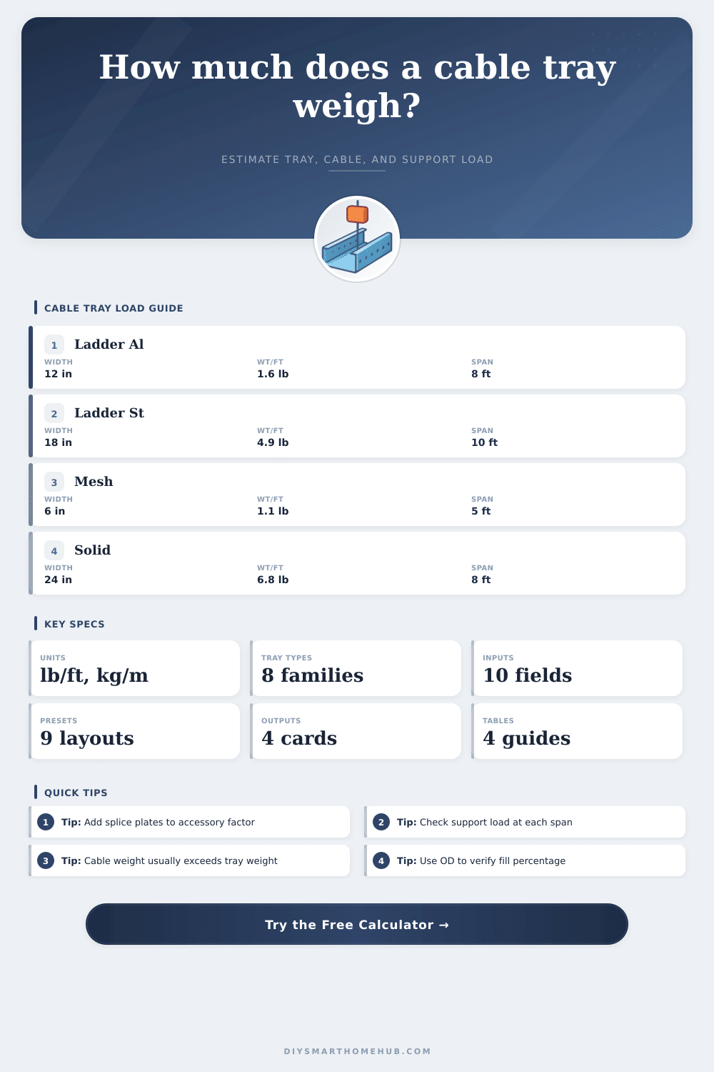
Estimate tray dead load, cable load, support reaction, and fill exposure for ladder, trough, basket, channel, and solid-bottom tray runs before hangers or trapeze supports are sized.
The calculator uses lineal tray self-weight plus the entered cable weight per unit length. Fill percentage is checked from cable outside diameter so you can compare cross-sectional packing against side rail depth.
Load Breakdown
| Tray Family | Typical Self-Weight | Reference Rated Load | Best Fit | Open Area |
|---|---|---|---|---|
| Aluminum ladder | 1.6-3.4 lb/ft | 60 lb/ft at 10 ft | Long indoor feeder runs | 58% |
| Steel ladder | 3.8-6.4 lb/ft | 75 lb/ft at 10 ft | Power and MCC feeders | 52% |
| Stainless ladder | 4.4-7.1 lb/ft | 70 lb/ft at 8 ft | Washdown or corrosive zones | 50% |
| Ventilated trough | 4.2-6.9 lb/ft | 65 lb/ft at 8 ft | Mixed control and power | 34% |
| Solid-bottom tray | 5.1-8.1 lb/ft | 62 lb/ft at 8 ft | EMI shielding and debris control | 18% |
| Wire mesh basket | 0.9-2.2 lb/ft | 18 lb/ft at 5 ft | Data, fiber, and low-voltage | 72% |
| Fiberglass ladder | 2.4-4.5 lb/ft | 55 lb/ft at 10 ft | Chemical and coastal spaces | 48% |
| Channel tray | 0.8-1.7 lb/ft | 12 lb/ft at 6 ft | Single cable or small bundles | 40% |
| Cable Example | Typical OD | Weight Each | Lineal Density | Common Tray Use |
|---|---|---|---|---|
| Cat6 plenum | 0.25 in | 0.04 lb/ft | 0.06 kg/m | Office data basket |
| 4C control 12 AWG | 0.52 in | 0.12 lb/ft | 0.18 kg/m | Control trough |
| 4/0 feeder single | 0.88 in | 0.63 lb/ft | 0.94 kg/m | Ladder feeder tray |
| 500 kcmil single | 1.20 in | 1.10 lb/ft | 1.64 kg/m | MCC and service tray |
| PV string cable | 0.30 in | 0.05 lb/ft | 0.07 kg/m | Solar trough |
| Fiber trunk cable | 0.64 in | 0.16 lb/ft | 0.24 kg/m | Campus backbone tray |
| Support Span | Steel Ladder Capacity | Aluminum Ladder Capacity | Basket Capacity | Design Note |
|---|---|---|---|---|
| 5 ft | 300% | 240% | 100% | Short spans sharply reduce bending stress |
| 8 ft | 156% | 125% | 39% | Good balance for corridor work |
| 10 ft | 100% | 100% | 25% | Typical reference catalog span |
| 12 ft | 69% | 69% | 17% | Use only if tray class supports it |
| 15 ft | 44% | 44% | 11% | Long spans demand deep side rails |
| Project Layout | Tray Setup | Cable Mix | Approx Load | What Usually Drives Weight |
|---|---|---|---|---|
| Office branch corridor | 12 in steel ladder | 24 branch circuits | 14-18 lb/ft | Cable bundle weight |
| Data hall overhead | 18 in basket | 72 Cat6 trunks | 4-6 lb/ft | Fill area before span load |
| Solar combiner row | 8 in trough | 40 PV strings | 7-10 lb/ft | Accessory and cover weight |
| Industrial feeder bank | 24 in steel ladder | 12 large singles | 24-32 lb/ft | Large conductor density |
| Hospital imaging path | 24 in solid-bottom | Shielded power and data | 18-24 lb/ft | Heavier tray plus fill margin |
If a tray segment carries 22 lb/ft over a 10 ft span, each support sees about 110 lb before safety factors, seismic bracing, and concentrated drops are added.
A tray can be light enough for the supports but still too crowded for bend space and heat release, so review both the area fill result and the lineal load result together.
When you are thinking about designing a cable management system, you must calculate the total weight of the ladder tray and the total weight of the cables. The weight of the cables are likely to be much greater then the weight of the ladder tray. Furthermore, the weight of the cables will dictate the total load that the ladder tray will have to bear when in operation.
If you dont take the weight of the cables into consideration, the tray may sag and the rod hanger may fail. The material of the tray will play a big role in the weight of the tray. For instance, aluminum tray will be much lighter than steel trays.
How to Calculate Cable Tray Weight and Load
Furthermore, installers will find aluminum trays easier to handle when installing the trays. Steel trays, however, will be stronger and able to handle the loads of heavy motor control center that are common in those areas. Wire mesh basket trays is very light and allow heat to escape from fiber optic cables.
Trough trays are designed with ventilated bottoms that allow for airflow through the tray. Each of these tray types have a different requirement for the distance between the supports. Another important consideration is the fill percentage of the tray.
The percentage will help determine how much of the tray is to be taken up by the cables. Furthermore, if the percentage fill reaches 40%, there should be enough room in the tray for the bends in the cables and for any future installation of additional cables. At 60% fill, there will be heat buildup within the tray that could damage the cables.
In order to prevent the cables from overheating, it is important to calculate the cross-sectional area of the cables to ensure they dont use too much of the usable area of the tray. In addition to the trays and the cables, there are a few accessories that will add to the total weight of the tray system. For instance, splice plates, dividers and covers can add as much as 15% to the total weight of the tray system.
You will have to account for these accessories in determining the weight of each trapeze span. Support reaction can be determined from the total load per span. Each half of a tray run will have half of the total load that the run will have to bear.
For instance, if the run weighs 20 pounds per foot and the run is 10 feet in length, then each of the rod hangers will have to support 100 pounds of load (half of the total load of 200 pounds). Furthermore, you can use span tables to determine the capacity of the ladder tray. For example, the capacity of a steel ladder tray will be less as the distance between supports increases.
A steel tray, for instance, may be able to hold its full load at a 10-foot span but may only be able to support 70% of its load at a 12-foot span. It is important to accurately calculate the weight of each of the cables in the system. For instance, the weight per foot of a small branch circuit is relatively low but there will be a high weight if there are many branch circuits with similar loads.
The weight per foot of a single large conductor is high but if there are many of those large diameter cables, the trays will be heavily loaded. Furthermore, you will have to calculate the average weight of the cables in the tray system carefully to ensure the small control cables are not affecting the average weight of the cables in the system. Finally, the outside diameter of the cables will have to be calculated to ensure that the load calculated for the cables does not exceed the usable area of the tray.
Some of the mistakes that must be avoided when designing the tray system include only considering the weight of the tray itself. Many people do not consider the additional weight of the cables which will likely be three times the weight of the tray. Furthermore, people often visually estimate the spans between the rod hangers rather than calculating the weight of the accessories for the trays.
Finally, the height of the side rail of the tray will affect the tray system as well; the greater the height of the side rail, the more the tray will be filled with cables and the more resistance it will exhibit against deflection. The environmental factors will also help determine the specifications for the trays. For instance, in areas where the load from the wind is likely to impact the tray, uplift must be considered.
In environments that are likely to be corrosive, trays made of stainless steel or fiberglass will be required. In environments where electromagnetic interference with other systems is a problem, a solid-bottom tray can be used but this will limit the ability of the tray to vent heat from the cables. Finally, trays that are made out of aluminum will expand faster than those made out of steel; thus, if the environment is likely to experience temperature changes, close together supports will be required to accommodate for this.
Each of these factors creates a 20% reserve load that should be included in the calculations of the lineal load of the tray system to ensure the safety of the system and its components.